9-14 VersaMax® Modules, Power Supplies, and Carriers User's Manual – March 2003 GFK-1504K
9
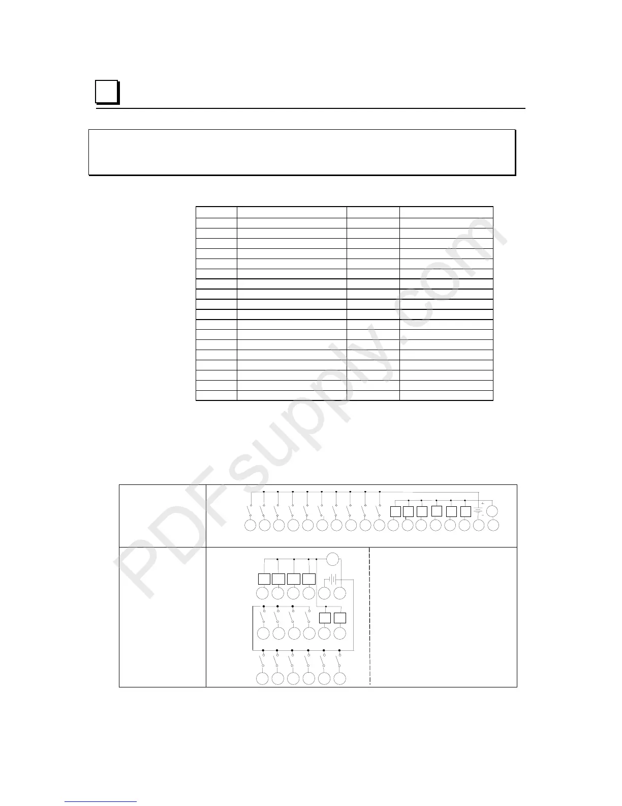
IC200MDD843
Mixed Module, 24VDC Positive Logic Input Grouped 10 Points /
Output Relay 2.0A per Point Grouped 6 Points
Field Wiring
Terminal Connection Terminal Connection
A1 Input 1 B1 No connection
A2 Input 2 B2 No connection
A3 Input 3 B3 No connection
A4 Input 4 B4 No connection
A5 Input 5 B5 No connection
A6 Input 6 B6 No connection
A7 Input 7 B7 No connection
A8 Input 8 B8 No connection
A9 Input 9 B9 No connection
A10 Input 10 B10 No connection
A11 Output 1 B11 No connection
A12 Output 2 B12 No connection
A13 Output 3 B13 No connection
A14 Output 4 B14 No connection
A15 Output 5 B15 No connection
A16 Output 6 B16 No connection
A17 Inputs 1-10 Common B17 No connection
A18 Outputs 1-6 Common B18 No connection
If additional bussed terminals are needed, the B terminals can be made available by using a
shorting bar. The shorting bar has a maximum current-carrying capacity of 2 Amps per
point. See chapter 2 for additional information about using the shorting bar. When wiring
outputs to inductive loads, use of external suppression circuits is recommended. See
chapter 2, "Installing Wiring for I/O Devices-Wiring to Inductive Loads" for more
information.
Wiring Connections
for Carriers with Two
Rows of Terminals
IC200CHS002, 005
IC200CHS012, 015
I1 I2
I3 I4 I5 I6 I7 I8
9I10
Q1
Q2 Q3
Q4
Q5 Q6
V
1 2 3 4 5 6 7 8 9 11 12 13 14 15 16 17 1810
A
Wiring Connections
for Carriers with
Three Rows of
Terminals
IC200CHS001, 022, 025
IC200CHS011
123456
789 111210
A
13 14 15 16 17 18
I1 I2 I3 I4 I5 I6
Q3 Q4 Q5 Q6
+
-
Q1 Q2
I7 I8 I9 I10
V