9-36 VersaMax® Modules, Power Supplies, and Carriers User's Manual – March 2003 GFK-1504K
9
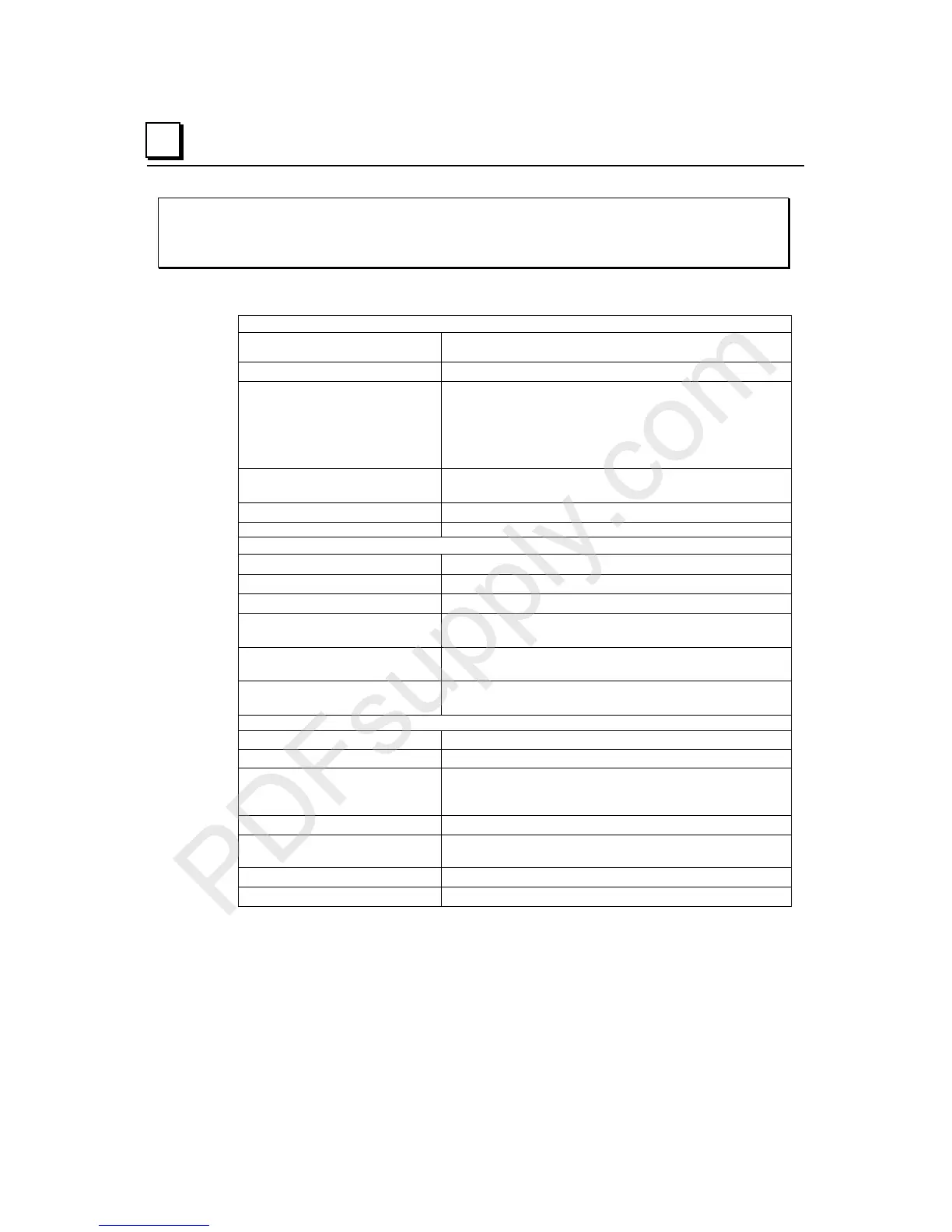
IC200MDD848
Mixed Module, Output 120VAC 0.5A per Pt Isolated 8 Points /
Input 120VAC Grouped 8 Points
Module Specifications
Module Characteristics
Points 8 Positive AC Inputs, one group.
8 Individually-isolated Outputs.
Module ID 88048840
Isolation:
User input/output to logic
(optical) and frame ground
Group to group
Point to point
250VAC continuous; 1500VAC for 1 minute
250VAC continuous; 1500VAC for 1 minute
Outputs: 250VAC continuous; 1500VAC for 1 minute
Inputs: none
LED indicators One LED per point shows individual point on/off state
OK LED indicates backplane power is present
Backplane current consumption
5V output: 125mA maximum
Thermal derating See diagram
Input Characteristics
Input voltage 0 to 132VAC (47 to 63Hz), 120VAC nominal
On state voltage 70 to 132VAC
Off state voltage 0 to 20VAC
On state current
Off state current
5mA minimum
2.5mA maximum
On response time
Off response time
1 cycle maximum
2 cycles maximum
Input impedance 8.6kOhms (reactive) at 60Hz, typical
10.32kOhms (reactive) at 50Hz, typical
Output Characteristics
Output voltage 85 to 132 VAC (47 to 63Hz), 120VAC nominal
Output voltage drop 2.0V maximum
Load current 10mA minimum per point
0.5A maximum per point
5.0A for one cycle (20ms) maximum inrush
Output leakage current Less than 2mA at 132VAC
On response time
Off response time
Less than ½ cycle, maximum
Less than ½ cycle, maximum
Protection Snubber and MOVs (each output)
Diagnostics None