9-46 VersaMax® Modules, Power Supplies, and Carriers User's Manual – March 2003 GFK-1504K
9
IC200MDD850
Mixed Module, Output Relay 2.0A per Pt Isolated 8 Points /
Input 240VAC Isolated 4 Points
Field Wiring
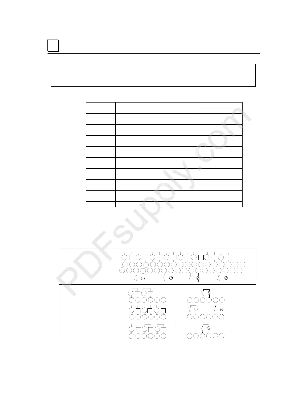
Terminal Connection Terminal Connection
A1 Output 1-1 B1 No connection
A2 Output 1-2 B2 No connection
A3 Output 2-1 B3 Input 1
A4 Output 2-2 B4 Input 1 Return
A5 Output 3-1 B5 No connection
A6 Output 3-2 B6 No connection
A7 Output 4-1 B7 Input 2
A8 Output 4-2 B8 Input 2 Return
A9 Output 5-1 B9 No connection
A10 Output 5-2 B10 No connection
A11 Output 6-1 B11 Input 3
A12 Output 6-2 B12 Input 3 Return
A13 Output 7-1 B13 No connection
A14 Output 7-2 B14 No connection
A15 Output 8-1 B15 Input 4
A16 Output 8-2 B16 Input 4 Return
A17 No connection B17 No connection
A18 No connection B18 No connection
Outputs are individually isolated. This module should be used with a compact terminal-
style carrier (IC200CHS022 or 025) or with a terminal-style carrier (IC200CHS001, 002,
005 suffix “B” or higher). It cannot be used with a Connector-Style Carrier
(IC200CHS003) due to its high isolation requirement. When wiring outputs to inductive
loads, use of external suppression circuits is recommended. See chapter 2, "Installing
Wiring for I/O Devices-Wiring to Inductive Loads" for more information.
Wiring Connections
for Carriers with Two
Rows of Terminals
IC200CHS002, 005
I1 I2
I3 I4
Q1 Q2 Q3 Q4 Q5 Q6 Q7 Q8v v v v v v v v
123456789 1112131415161718
123456789 111213141516171810
10
B
A
N
N
N
N
Wiring Connections
for Carriers with
Three Rows of
Terminals
IC200CHS001, 022, 025
123456
123456
13
14 15 16 17 18
789 111210
A
13 14 15 16 17 18
789 111210
B
Q4 Q5 Q6
Q7 Q8
vvv
vv
Q1 Q2 Q3
vv
v
I1
I2
I3
I4
N
N
N
N