10-18 VersaMax® Modules, Power Supplies, and Carriers User's Manual – March 2003 GFK-1504K
10
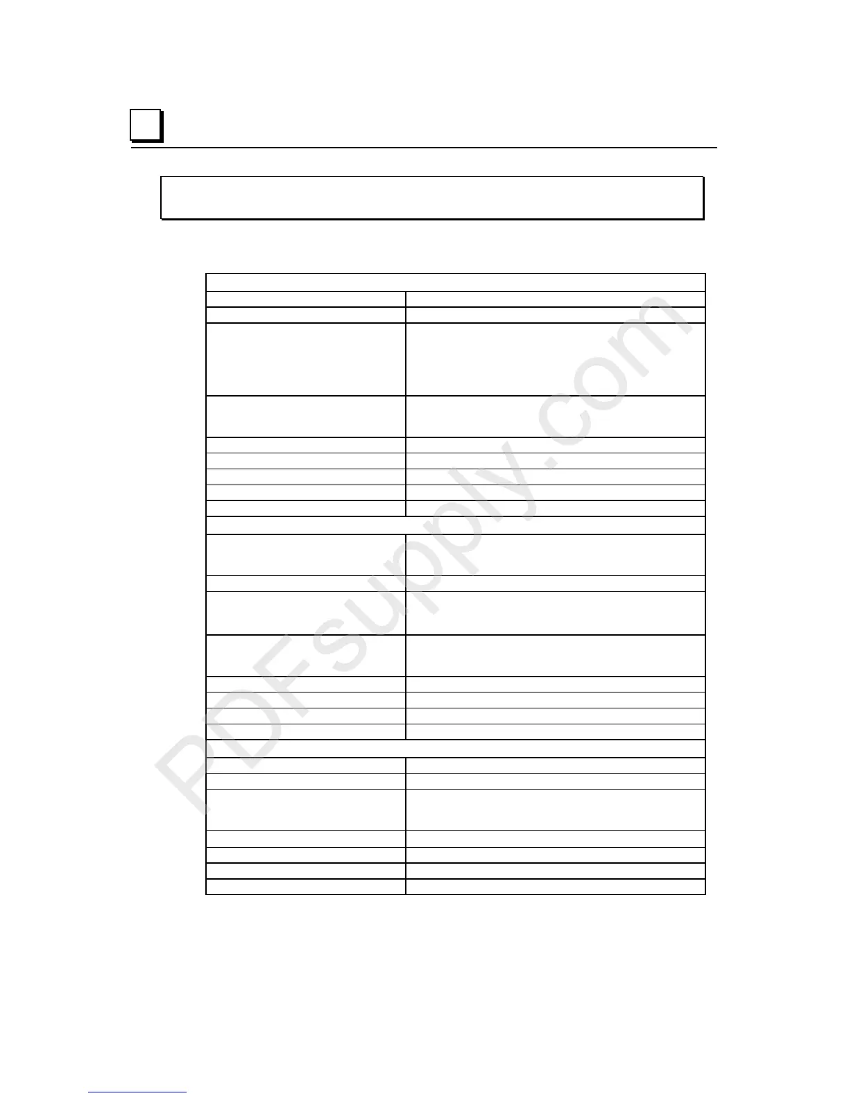
IC200ALG260
Analog Input Module, 12 Bit Voltage/Current 8 Channels
Module Specifications
Module Characteristics
Channels 8 single ended, one group
Module ID FFFF9008
Isolation:
User input to logic (optical) and to
frame ground
Group to group
Channel to channel
250VAC continuous; 1500VAC for 1 minute
Not applicable
None
LED indicators INT PWR LED indicates internally-generated field power is
present
OK LED indicates backplane power is present
Backplane current consumption 5V output: 130mA maximum
External power supply None
Thermal derating None
Configuration parameters Range select, Mode select (jumpers on carrier)
Diagnostics Loss of Internal Power
Input Characteristics: Voltage Mode (default)
Input voltage:
Bipolar
Unipolar
+/-10VDC (default)
0 to 10V (configurable)
Input Impedance 126kOhms maximum
Accuracy at:
25 degrees C*
0 to 60 degrees C
+/-0.3% typical of full scale, +/-0.5% maximum of full scale
+/-1% maximum of full scale
Resolution:
Bipolar mode:
Unipolar mode:
2.5mV = 8 counts
2.5mV = 8 counts
Filter response 5.0ms
Update rate per module 0.4ms
Common mode voltage 0 V
Channel-to-channel crosstalk rejection 30dB minimum
Input Characteristics: Current Mode
Input current 4 to 20mA
Input Impedance 200 Ohms maximum
Accuracy at:
25 degrees C*
0 to 60 degrees C
+/-0.3% typical of full scale, +/-0.5% maximum of full scale
+/-1% maximum of full scale
Resolution
4
µ
A = 8 counts
Filter response 5ms
Update rate per module 0.4ms
Channel-to-channel crosstalk rejection 30dB minimum
*
In the presence of severe RF interference, (IEC 1000-4-3, 10V/m), accuracy may be degraded to +/-3%.