GFK-1504K Chapter 10 Analog Input Modules 10-25
10
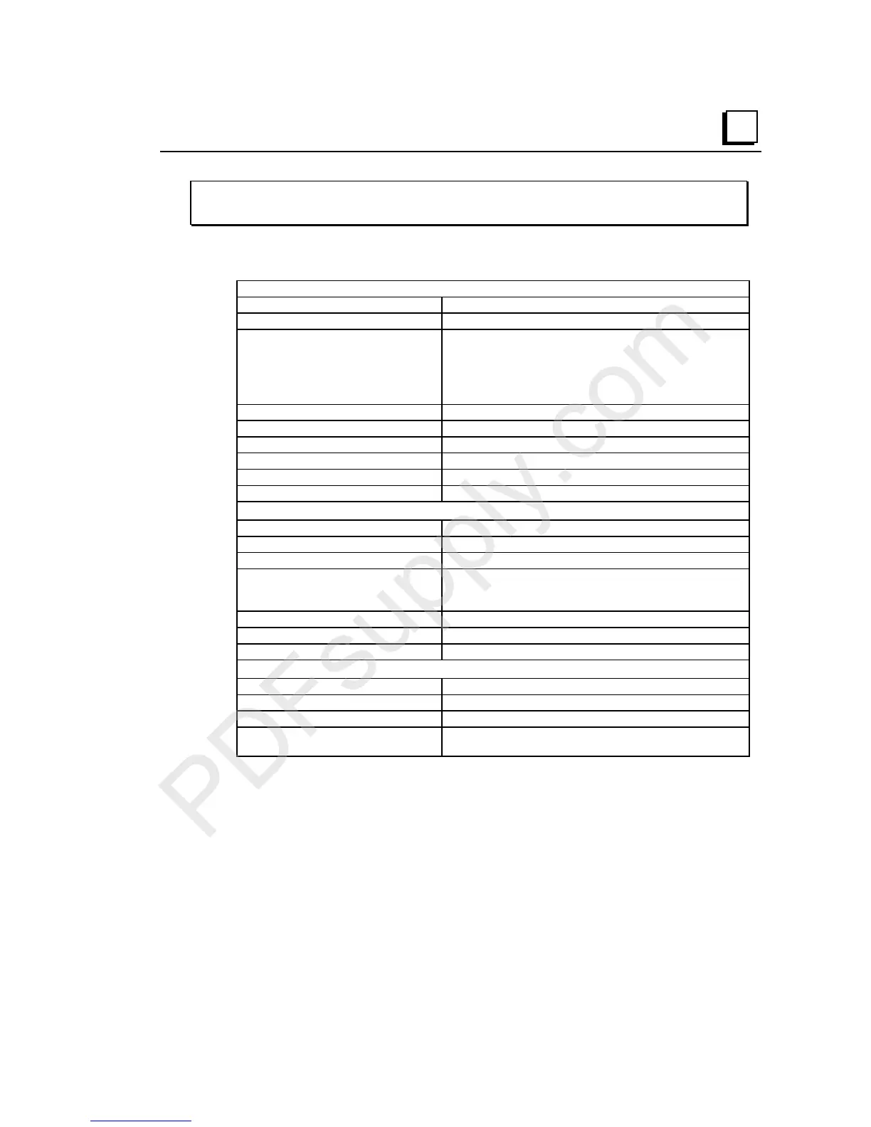
IC200ALG261
Analog Input Module, 15 Bit Differential Voltage 8 Channels
Module Specifications
Module Characteristics
Channels 8 differential, one group
Module ID FFFFB008
Isolation:
User input to logic (optical) and to
frame ground
Group to group
Channel to channel
250VAC continuous; 1500VAC for 1 minute
Not applicable
None
LED indicators OK LED indicates backplane power is present
Backplane current consumption 5V output: 200mA maximum
External power supply None
Thermal derating None
Configuration parameters None
Diagnostics Loss of Internal Power
Input Characteristics
Input Voltage (Differential) -10V to +10V
Input Voltage (Common Mode) -10V to +10V
Input Impedance 100K ohms minimum
Accuracy (0V common mode):
25 degrees C*
0 to 60 degrees C
+/-0.3% typical of full scale, +/-0.5% maximum of full scale
+/-1% maximum of full scale
Resolution 0.3125mV = 1 count
Common mode rejection 70db
Update rate per module 7.5ms
Compatibility
VersaPro Software Version 2.0 or higher
VersaMax PLC CPU Firmware Version 2.10 or higher
VersaMax Ethernet NIU Firmware Version 1.10 or higher
VersaMax DeviceNet, Profibus, or
Genius NIU Firmware
Planned for future release
*
In the presence of severe RF interference, (IEC 1000-4-3, 10V/m), accuracy may be degraded to +/-1%. Input
accuracy may be degraded an additional +/-1% with the introduction of input common mode voltage.