11-24 VersaMax® Modules, Power Supplies, and Carriers User's Manual – March 2003 GFK-1504K
11
IC200ALG325
Analog Output Module, 13 Bit Voltage 8 Channels
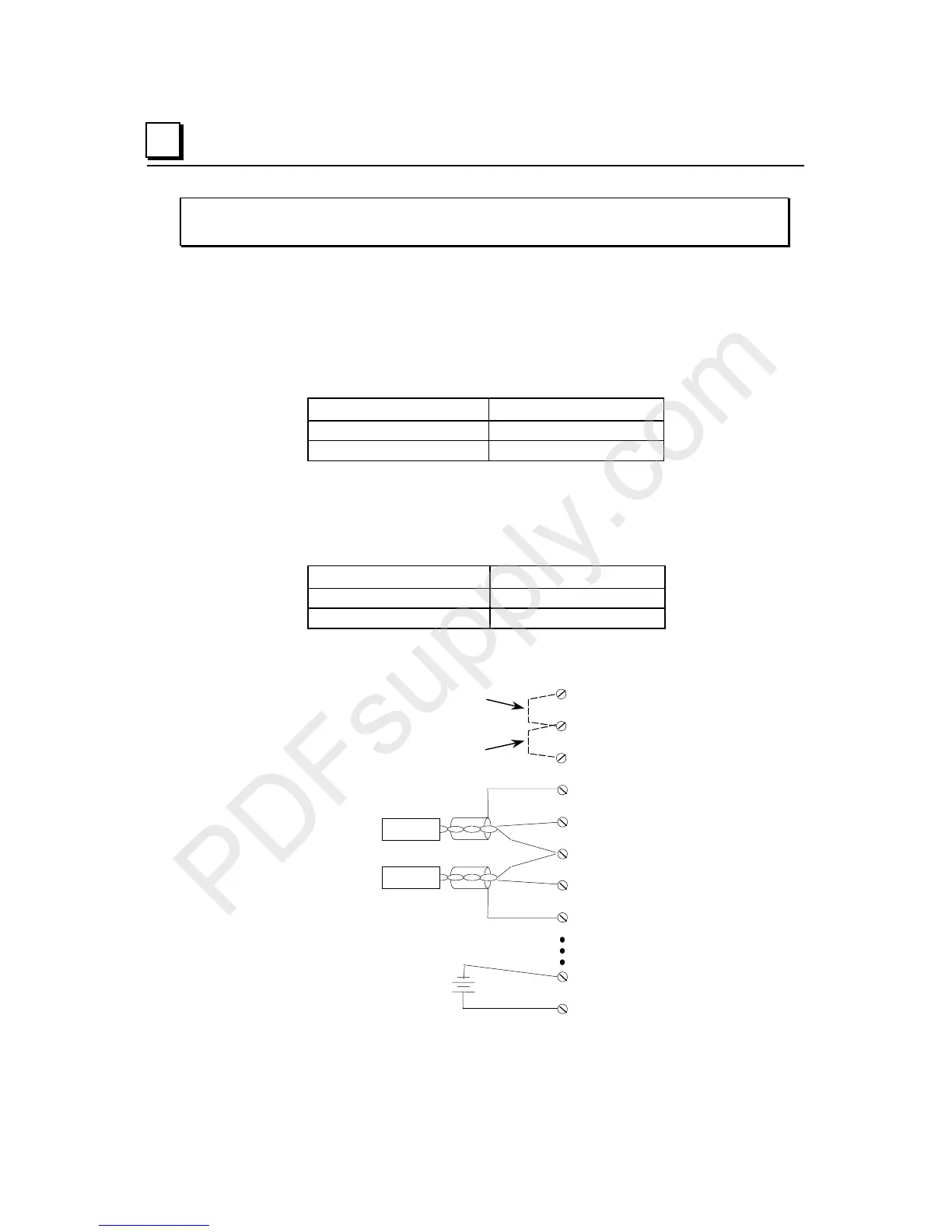
Jumper Selection
Jumpers on the carrier can be used to select the output range and output default mode.
Range Jumper
If no jumper is installed on pins B1 and B2, outputs are configured for the bipolar range of
–10V to +10V. With a jumper installed, the outputs are configured for the unipolar range
of 0V to +10V.
Range Jumper (JMP 1) Range
None -10V to +10V
Installed 0V to +10V
Hold Jumper
If no jumper is installed on pins B2 and B3, outputs hold their last state (the last
commanded value from the backplane) if backplane power or communications are
interrupted or the PLC is stopped. With a jumper installed, outputs default to 0V. This
should only be changed with the field power and backplane power removed.
Hold Jumper (JMP 2) Output Default
None Hold Last State
Installed 0V
Wiring Example
JMP 2
Jumper installed = unipolar range
no jumper = bipolar range
JMP 1
Field Power
Field Return
-
+
Load 1
Shield
V OUT 1
Return 1, 2
Load 2
V OUT 2
Shield
RET
Jumper installed = default to 0V
no jumper = hold last state