GFK-1504K Chapter 11 Analog Output Modules 11-29
11
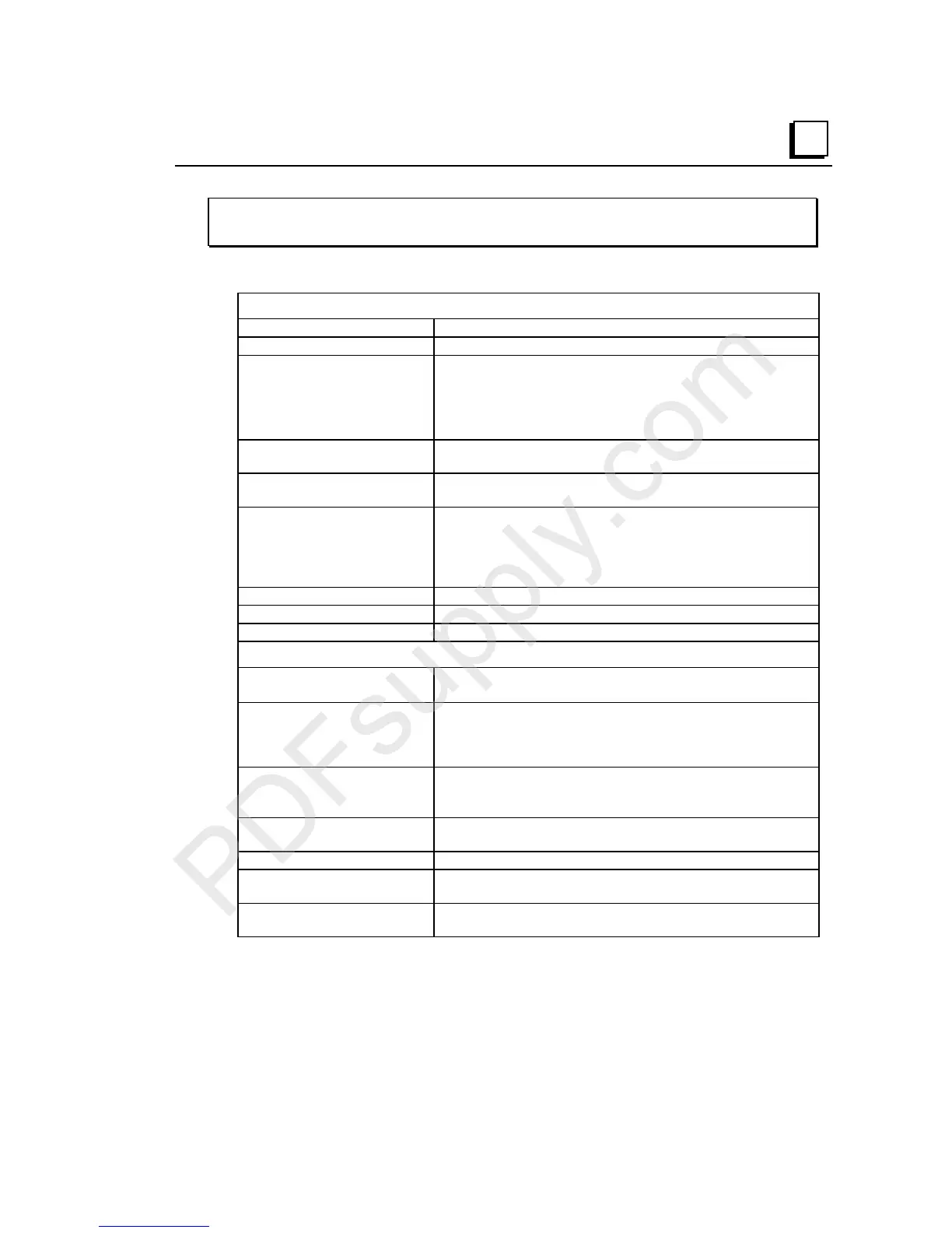
IC200ALG326
Analog Output Module, 13 Bit Current, 8 Channels
Module Specifications
Module Characteristics
Channels 8 single-ended, one group
Module ID FFFF9480
Isolation:
User input to logic and to
frame ground
Group to group
Channel to channel
250VAC continuous; 1500VAC for 1 minute
Not applicable
None
LED indicators FLD PWR LED indicates field power is present
OK LED indicates backplane power is present
Backplane current
consumption
5V output: 50mA maximum
External power supply:
Range
Current consumption
+18 to +30VDC (including ripple)
2A inrush maximum
100 mA maximum (no load)
185 mA maximum (all 8 outputs at full scale)
Thermal derating None
Configuration parameter Range, output default
Diagnostics Loss of User Side (Field) Power
Output Characteristics
Output current 4 to 20mA (default)
0 to 20mA (configured with jumper)
Load characteristics:
Resistive
Capacitive
Inductive
0 to 800 Ohms maximum*
0.1µF maximum
0.5H maximum
Accuracy:
+25 deg C**
0 to +60 degrees C
+/- 0.3% of full scale (typical), +/- 0.5% of full scale (max)
+/-1% of full scale (max)
Resolution 4-20 mA: 5 counts = 2.5 uA (~12.7 bits)
0-20 mA: 4 counts = 2.5 uA (13 bits)
Update rate per module 15 mSec maximum
Channel-to-channel crosstalk
rejection
70dB minimum
Output default Hold Last State (default)
Low End of Range (configurable)
* R
L(MAX)
= (V
FIELD PS
– 4V) / 20.38mA
** In the presence of severe RF interference, (IEC 1000-4-3, 10V/m), accuracy
may be degraded an additional +/-1%.

 Loading...


