11-44 VersaMax® Modules, Power Supplies, and Carriers User's Manual – March 2003 GFK-1504K
11
IC200ALG328
Analog Output Module, 13 Bit Current, 12 Channels
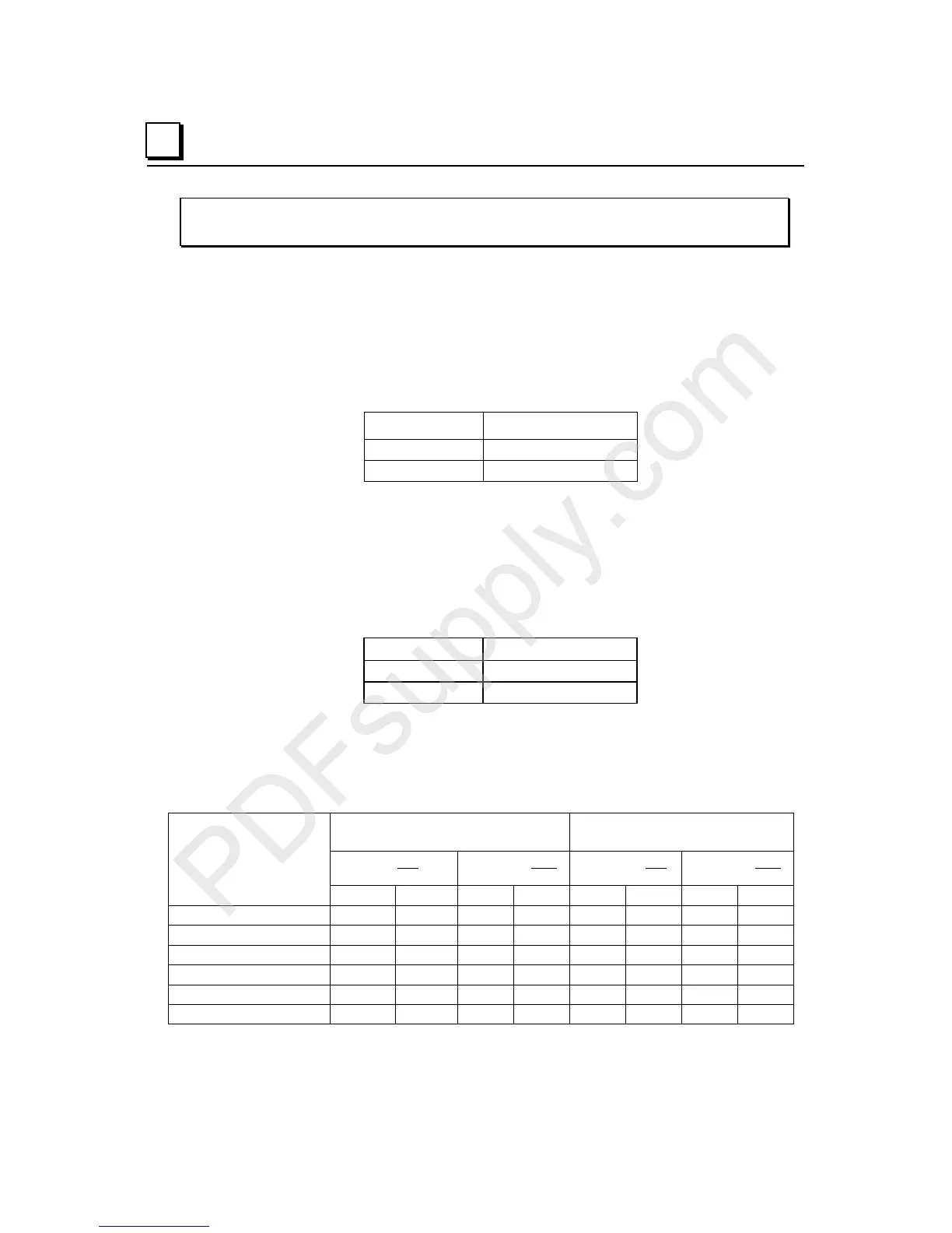
Jumper Selection
Range Jumper
If no jumper is installed the output current range will be 4 to 20 mA. With a jumper
installed the output current range is 0 to 20 mA. This should only be changed with field
power and backplane power removed. The corresponding parameter in the hardware
configuration must also be adjusted accordingly.
Range Jumper Default
None 4 to 20 mA
JMP 1 0 to 20 mA
Hold Jumper
If no jumper is installed outputs hold their last states (the last commanded values from the
backplane) if backplane power or communications are interrupted or the PLC is stopped.
With a jumper installed, if such conditions occur outputs default to 0/4mA. This should
only be changed with field power and backplane power removed. The corresponding
parameter in the hardware configuration must also be adjusted accordingly.
Hold Jumper Default
None Hold Last State
JMP 2 0/4mA
The “Default Low End of Range” value can be either 4mA or 0mA. The default depends
on the PLC status, output current range selected, and whether the module is controlled by a
VersaMax PLC CPU or a Network Interface Unit (NIU) module. In some cases, the
module will output 0mA instead of 4mA, even when configured for the 4-20mA range as
shown in the following chart.
Module Set to Default
Low End of Range (Default)
Module Set to
Hold Last State (HLS)
Action
Module in NIU Rack Module in CPU
Rack
Module in NIU
Rack
Module in CPU
Rack
0-20mA 0-20mA 4-20mA 0-20mA 4-20mA 4-20mA 0-20mA 4-20mA
Run to Stop 0mA 0mA 4mA 0mA HLS HLS HLS HLS
Loss of Field Power 0mA 0mA 0mA 0mA 0mA 0mA 0mA 0mA
Loss of Backplane Power 0mA 0mA 0mA 0mA HLS HLS HLS HLS
Loss of Communication 0mA 0mA 4mA N/A HLS HLS N/A N/A
Loss of Module 0mA 0mA 0mA 0mA 0mA 0mA 0mA 0mA
Loss of CPU/NIU Power 0mA 0mA 0mA 0mA HLS HLS HLS HLS