GFK-1504K Chapter 13 Mixed Discrete/High-speed Counter Module 13-5
13
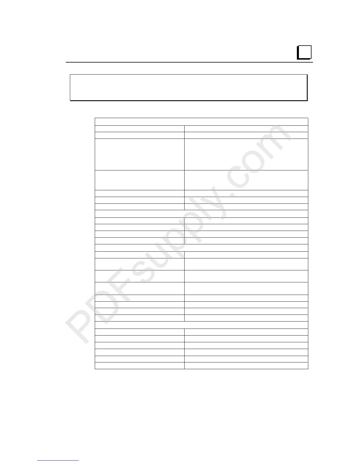
IC200MDD841
Mixed Module, 24VDC Positive Logic Input 20 Points / Output 12 Point /
(4) High Speed Counter, PWM, or Pulse Train Configurable Points
Module
Specifications
Module Characteristics
Points 20 DC inputs & 12 DC outputs
Module ID FFFF9801
Isolation:
User I/O to logic (optical) and to frame
ground
Point to point
Group to group
250VAC continuous, 1500VAC for 1 minute
250VAC continuous, 1500VAC for 1 minute
Indicators One LED per point shows individual point on/off state
FLD PWR indicates field power is present
OK LED indicates backplane power is present.
Backplane current consumption 3.3V output: 130mA, 5V output: 30mA
External power supply +24VDC nominal, +18 to +30VDC
Thermal derating See diagrams
High Speed Channels
Input frequency (Type A Counter 80KHz maximum
PWM Output frequency 2 KHz maximum
Pulse Output frequency 5 KHz maximum
Counter Output latency 0.5mS max. between output point updates
Input Characteristics
Input voltage +24VDC nominal, 0 to +30VDC
On state voltage
Off state voltage
+15.0 to +30.0VDC
0 to +5.0 VDC
On state current
Off state current
3.0 to 8.0mA
0 to 0.5mA
On/off response time
7.0ms max. (6.25
µ
s max. for count inputs and 100
µ
s for
Preload/Strobe inputs)
Count Input Impedance 6.6kOhms maximum
Count User input current 5.5mA at +24VDC
Standard Input Impedance 9.6kOhms maximum
Standard User input current 4.0mA at +24VDC
Output Characteristics
Inrush current 2.0A maximum for 100ms
Continuous Load Current 0.5A maximum
Output voltage drop 0.3V maximum
On/off response time
500
µ
s, maximum
Protection no internal fuses
Diagnostics 13 words of status data