13-6 VersaMax® Modules, Power Supplies, and Carriers User's Manual – March 2003 GFK-1504K
13
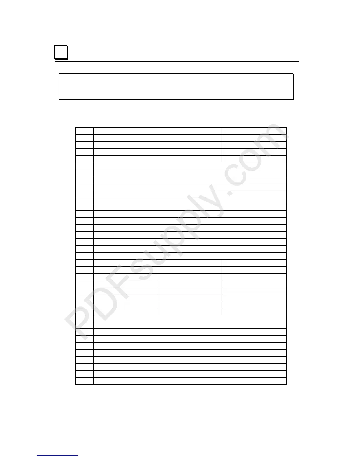
IC200MDD841
Mixed Module, 24VDC Positive Logic Input 20 Points / Output 12 Point /
(4) High Speed Counter, PWM, or Pulse Train Configurable Points
Field
Wiring
Terminal assignments for the module are shown below.
# 4 Type A Counters 2 Type A & 1 Type B 1 Type B2
A1 Counter 1 Output/PWM/PT1 Output 1/PWM/PT1 Output 1/PWM/PT1
A2 Counter 2 Output/PWM/PT2 Type B Counter 2 out/PWM/PT2 Type B2 Counter 2 out/PWM/PT2
A3 Counter 3 Output/PWM/PT3 Type A Counter Output/PWM/PT3 Output 3/PWM/PT3
A4 Counter 4 Output/PWM/PT4 Type A Counter Output/PWM/PT4 Output 4/PWM/PT4
A5 Output 5
A6 Output 6
A7 Output 7
A8 Output 8
A9 Output 9
A10 Output 10
A11 Output 11
A12 Output 12
A13 Input 17
A14 Input 18
A15 Input 19
A16 Input 20
A17 DC- for outputs 1-12 and inputs 17-20
A18 DC+ for outputs
B1 Count1 Type B: Phase 2 Type B2: Phase 2
B2 Preload/Strobe 1 not used not used
B3 Count2 Type B: Phase 1 Type B2: Phase 1
B4 Preload/Strobe 2 Type B: Preload/Strobe Type B2: Preload/Strobe
B5 Count3 Type A: Count not used
B6 Preload/Strobe3 Type A: Preload/Strobe Home Enable
B7 Count4 Type A: Count not used
B8 Preload/Strobe 4 Type A: Preload/Strobe Marker
B9 Input 9
B10 Input 10
B11 Input 11
B12 Input 12
B13 Input 13
B14 Input 14
B15 Input 15
B16 Input 16
B17 DC- Common for inputs 1- 8
B18 DC- Common for inputs 9-16