14-4 VersaMax® Modules, Power Supplies, and Carriers User's Manual – March 2003 GFK-1504K
14
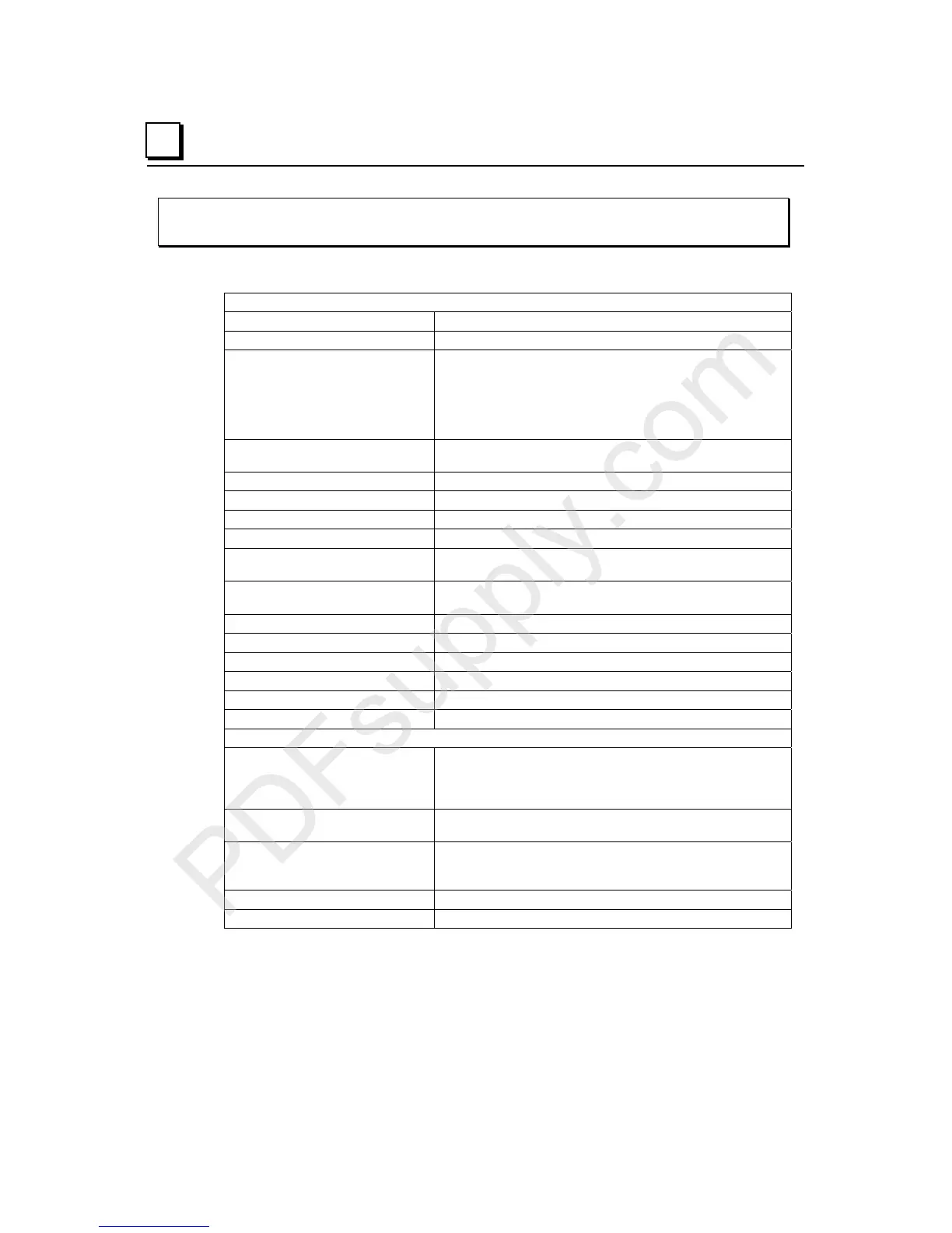
IC200ALG620
Analog Input, 16 Bit RTD, 4 Channels
Module Specifications
Module Characteristics
Channels Four 3-wire and/or 4-wire RTDs
Module ID
Isolation:
User input to logic (optical) and
to frame ground
Group to group
Channel to channel
250VAC continuous; 1500VAC for 1 minute
Not applicable
50VDC
LED indicators OK LED: green indicates backplane power is present. Amber
indicates module fault.
Backplane current consumption 5V output: 125mA maximum. 3.3V output: 125mA
External power supply None
Thermal derating None
Configuration parameters See configuration table
Diagnostics Over/under range, open wire, non-volatile memory storage
fault, wiring fault, high/low alarm, input short
Update rate 60 Hz: approximately 210 milliseconds per channel
50 Hz: approximately 230 milliseconds per channel
Normal mode rejection 60dB, at 50/60 Hz, 100% span
Common mode rejection 120 dB at 50/60Hz, 100 ohm imbalance
Common mode voltage 3V maximum
Normal mode voltage 5V maximum
Digital Resolution 15 bits plus sign
Operating temperature range 0 to 60 Degrees C ambient
Input Characteristics
RTD types 25, 100, and 1000 ohm platinum
10, 50, and 100 ohm copper
100 and 120 ohm nickel
604 ohms nickel/iron
Resistance ranges 0 to 500 ohms
0 to 3000 ohms
Accuracy, at 25° C
on voltage measurement:
on temperature measurement:
+/–0.15% on resistance measurement
+/-0.15% on RTD (temperature) measurement
Temperature sensitivity (0° to 60°C) +/–0.004% of reading, +/–1.5µV per °C referred to input
Maximum lead resistance 5 ohms per lead