GE
D
IRECTION FQ091019, REVISION 2 VIVID Q N SERVICE MANUAL
Chapter 5 - Components and Function (Theory) 5-31
5-6-3 Power Supply Unit Components
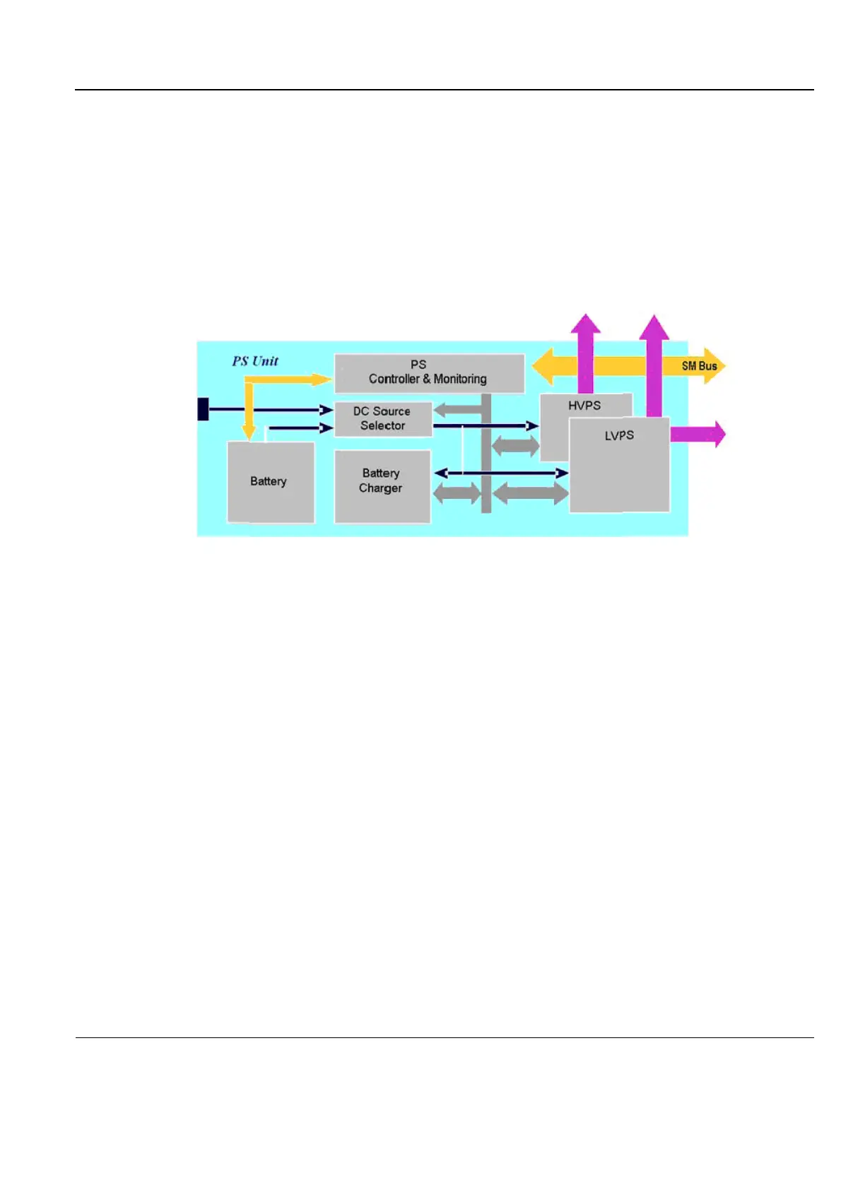
As shown in Figure 5-23 below, the Power Supply Unit comprises the following components:
• Rechargeable Battery
• PS Controller and Monitor
• DC Source Selector
• Battery Charger
• High Voltage Power Supply (HVPS)
• Low Voltage Power Supply (LVPS)
Figure 5-23 Vivid q N Power Supply Unit Components - Block Diagram
5-6-3-1 Critical Temperature Sensor
The PS Unit includes temperature sensors. When the monitoring application measures the maximum
temperature limit or above, it will shut down the system. After the temperature settles down, the PS unit
will enable the DC-DC operation.
5-6-4 DC Source Selector
This circuitry selects the source of the power. When the AC-to-DC converter input into the system is
higher than 18 V, the system will be powered by the AC-to-DC converter. Otherwise, the selector will
look for an alternative power source (the battery), expecting to receive between 12 and 16V DC.
 Loading...


