GE
D
IRECTION FQ091019, REVISION 2 VIVID Q N SERVICE MANUAL
8-22 Section 8-2 - External Component Replacement Procedures
8-2-6 LCD Display Cover Hinges Replacement Procedure
NOTE: This section describes the replacement procedure for the LCD Display Cover hinges only.
Refer to Figure 8-64 on page 8-55. (Part No. KTZ280195; one pair of hinges).
8-2-6-1 Tools
Phillips screwdriver; Loctite 242 glue
8-2-6-2 Time Required
15 minutes
8-2-6-3 Preparations
Shut down the Vivid q N ultrasound unit, as described in - System Setup.
8-2-6-4 LCD Display Cover Hinges Removal Procedure
1) Remove the bearing handle, as described in the "Bearing Handle Removal Procedure" on page 8-2.
2) Remove the Control Panel and Keyboard as described in the "Control Panel and Keyboard
Removal Procedure" on page 8-10.
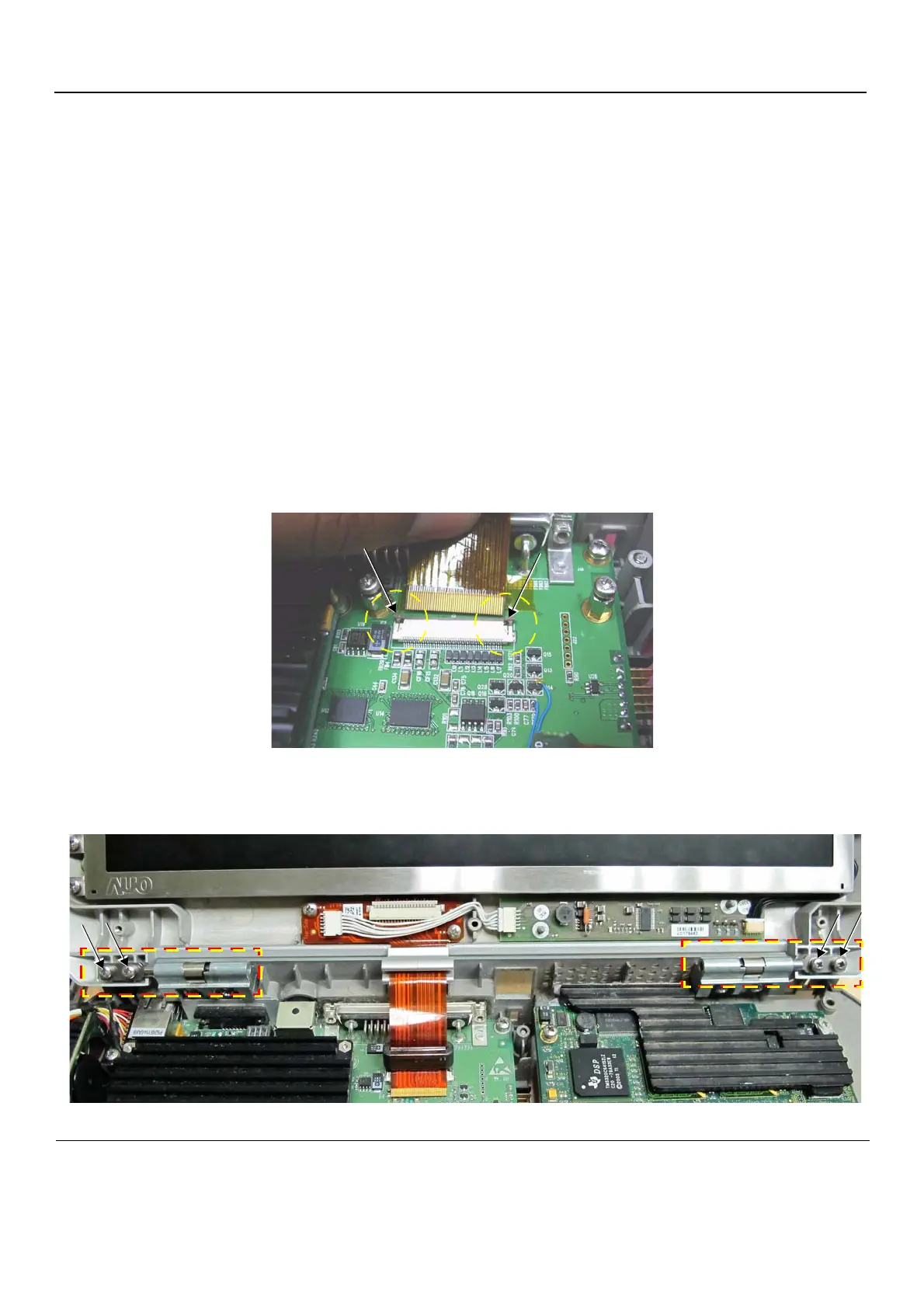
3.) Slide to open the two connector latches and disconnect the LCD Flex ribbon cable from BEP - Figure 8-25.
4.) Unscrew and remove the four screws (two on either side - as shown in Figure 8-26) that secure the
Rear Cover and Latch Assembly to the Bottom Assembly.
Figure 8-25 Connector Latches
Figure 8-26 Rear Cover and Latch Assembly Securing Screws
 Loading...


