ADV200 • Quick start up guide 187
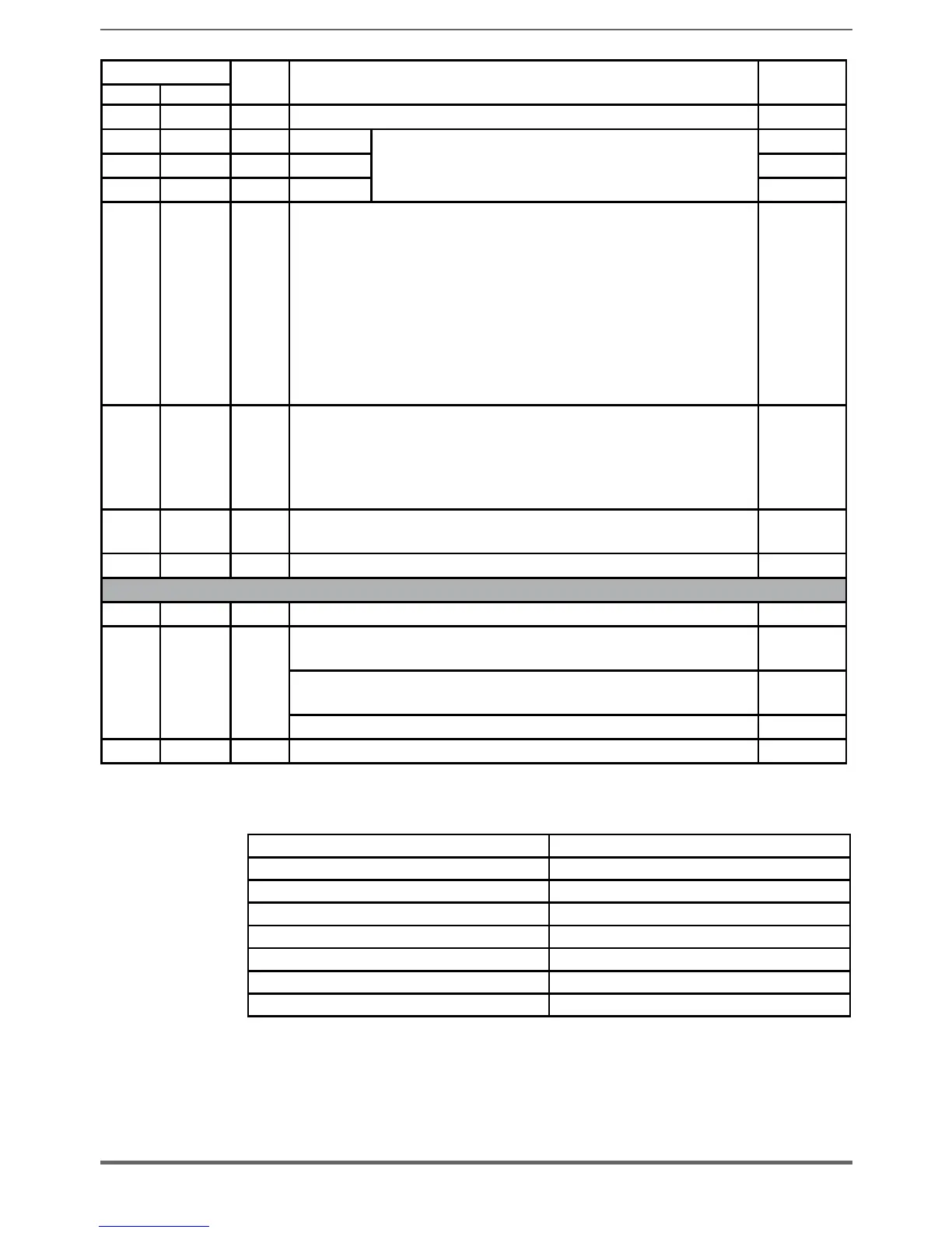
LEDS
Colour FUNCTION
Normal
functioning
≤ F (*) ≥ L (*)
H11 D127 Red It lights up to indicate overtemperature of the air inside the drive Off
H12 D132 Red IGBT U
They light up to indicate loss of the feedback signal relating
to the moment the IGBT devices are switched on. The
signal is used for hardware dead time compensation
Off
H13 D130 Red IGBT V Off
H14 D133 Red IGBT W Off
H15 D131 Red
It lights up in case of overtemperature of one of the IGBT devices.
The signal temperature relating to the hotter of the master and slave
IGBT devices is sent to the regulation card.
A temperature signal is also sent automatically to the regulation card in
case of minimum temperature, which could occur in the event of a fault
in one of the temperature reading circuits.
The loss of one of the temperature signals is indicated by LED H15,
with the code indicated by the number of flashes (*): the sequence of
flashes to indicate the faulty PHASE or SLAVE has a 3Hz frequency and
is repeated cyclically every 5 seconds.
Off
H18 D91 Red
It lights up on the INT-P-ADV MASTER card to indicate that the drive’s
total current (master + slave) has exceeded the overcurrent value for
the size of drive, whereas it lights up on the INT-P-ADV SLAVE card to
indicate that the SLAVE current has only exceeded the overcurrent value
of the SLAVE.
Off
H19 D95 Red
It lights up to indicate a fault on the DC-BUS power supply regulation
card
Off
D71 Red Overvoltage / Undervoltage safety supply Off
OPERATIONS
D148 Red FPGA active reset HW On
D152 Green
Active PWM from regulation and sent to power (master drive or single
drive only)
On
Active PWM from regulation but cancelled (master drive or single drive
only)
Blinking
Active PWM to power (master drive and single drive only) On
D74 Green Active PWM to power On
(*) HW revision of INT-P-ADV card
(*) Led H15 code indicated by number of flashes NO. FLASHES
PHASE U 1
PHASE V 2
PHASE W 3
SLAVE 1 4
SLAVE 2 5
SLAVE 3 6
SLAVE 4 7

 Loading...


