58 ADV200 • Quick start up guide
5.4 Encoder
The encoders may only be connected to the inverter when an EXP-...-ADV op-
tional card is installed.
For further details of the technical specications, refer to the EXP-...-ADV optional
card manual.
For instructions regarding fastening of the optional card, see paragraph 10.5 of this
manual.
Optional Card Code Encoder PAR 530 - 532 - 534
Slot X card type (*)
EXP-DE-I1R1F2-ADV S5L30 Incremental Digital Encoder (DE) Enc 1
EXP-DE-I2R1F2-ADV S5L35 Double Incremental Digital Encoder (2 x DE) Enc 7
EXP-SE-I1R1F2-ADV S5L31 Incremental Sinusoidal Encoder (SE) Enc 2
EXP-SESC-I1R1F2-ADV S5L32 Incremental Sinusoidal Encoder + SinCos Absolute (SESC) Enc 3
EXP-EN/SSI-I1R1F2-ADV S5L33 Incremental Sinusoidal Encoder + Endat Absolute + SSI (SE-EnDat/SSI) Enc 4
EXP-HIP-I1R1F2-ADV S5L34 Incremental Sinusoidal Encoder + Hiperface Absolute (SE-Hiperface) Enc 5
EXP-ASC-I1-ADV S5L42 Incremental SinCos Absolute Encoder Enc 8
EXP-RES-I1R1-ADV S5L43 Resolver Enc 9
(*) Enc X = name assigned to the card by the software, see PAR 530 - 532 - 534.
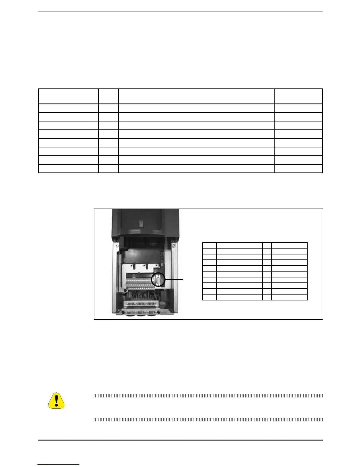
5.5 Serial interface (XS connector)
XS
Function I/O
Electr. interface
PIN1
Internal use ––
PIN2
Internal use ––
PIN3
RxA/TxA I/O RS485
PIN4
Equipotentiality (optional) ––
PIN5
0V (Ground for5V)
–
Power supply
PIN6
Internal use
–
–
PIN7
RxB/TxB I/O RS 485
PIN8
Internal use ––
PIN9
+5 V
–
Power supply
I=Input
O=Output
The ADV200 drive is equipped as standard with a port (9-pin D-SUB receptacle
connector: XS) for connection of the RS485 serial line used for drive/PC point-
to-point communication (through the GF-eXpress conguration software) or for
multi-drop connection.
To access the connector, remove the lower cover as illustrated in shown in para-
graph 5.2.1.
5.5.1 Drive / RS 485 Port (not insulated) point-to-point connection
The connection indicated is without galvanic insulation !
Le raccordement indiqué n’a pas d’isolation galvanique !
Caution

 Loading...


