ADV200 • Quick start up guide 39
The overtemperature switch can be connected to the auxiliary contacts of the
power supply contactor in order to disable the drive in case of failure.
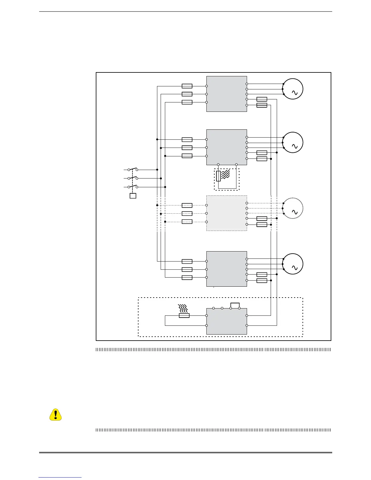
5.1.10 Parallel connection on the AC (Input) and DC (Intermediate Circuit)
side of several inverters
- The inverters used have to be all the same size.
- The mains power supply has to be simultaneous for all inverters, i.e. a single switch /line contactor has
to be used.
- Such connection is suitable for a maximum of 6 inverters.
- If necessary dissipate braking energy; a single internal braking unit (with external resistor) has to be
used or one (or several) external braking unit.
- Fast fuses (F12...F62) have to be tted on the dc-link side ( C and D terminals) of each inverters (see
chapter 10.1.2).
(*) Do not connect if external braking units BUy.. is used.
(*) Pas raccorder si l’unité de freinage extérieure BUy... est utilisée
Caution

 Loading...


