ADV200 • Quick start up guide 63
+ 24V
L1
M1
K1M
5
L1
L2
L3
N
PE
G1
0 V24
C
D
1
2
3
4
6
SMPS
COM ID
S3
C3
C2
12
7
Fault reset src
Digital input E mon
(Enable)
R11
R14
R21
R24
RS 485
S1+
S1-
C1
+ 10 V
- 10 V
0 V 10
1
2
Analog input 1Analog input 2
-
4
3
-
+
+
E
L2
L3
U
V
W
Null (not assigned)
FR reverse src
FR forward src
Analog
output 2
Analog
output 1
5
C1
6
13
IC1
COM Dig. Out.3/4
Dig. Out.3
M
3~
8
9
10
11
EXP-DE-...
(optional)
Dig. Output 2
(Relay 2)
Null (not assigned)
IS1
14
PS Dig. Out.3/4
Dig. Out.4
BR1
BR2
Braking resistor (optional)
Dig. Output 1
(Relay 1)
Drive OK
Drive ready
L1(*)F1
K2
K1M
K0
(**)
K2T
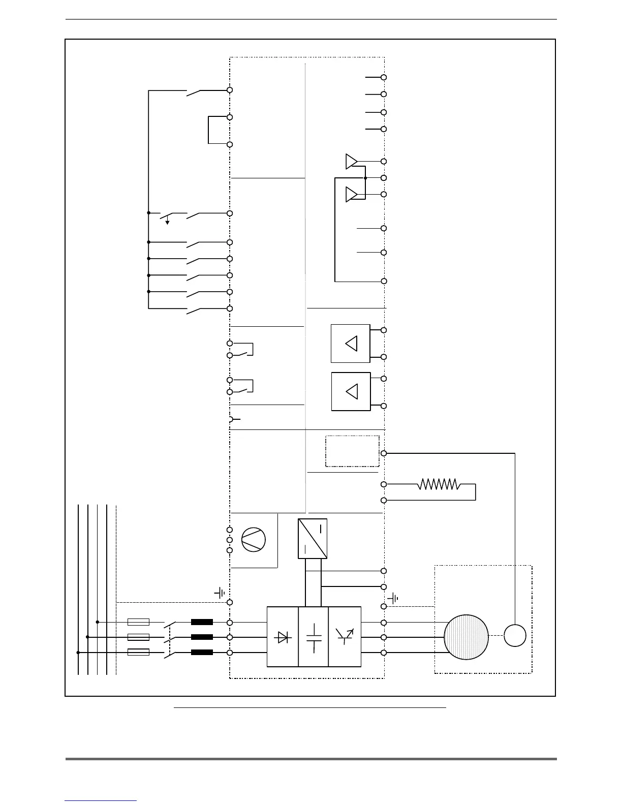
Figure 5.6.2: Typical connection diagram, connection through terminals strip
(*): ADV1007 ... 61320: Integrated choke on DC link; ≥ 716000: external choke mandatory;
(**) See chapter 5.1.12, Connection of fans.

 Loading...


