03-0X =05: Multi-speed/position setting command 4 (setting =05).
Select frequency reference using multi-function digital input.
In SV or PMSV mode (00-00=3, 4), with 03-00~07 set to 51, multi-speed command can be used to select multi-
ple segment positions.
03-0X =29: Jog frequency selection (setting =29). Select frequency reference using the multi-function digital
input. In SV or PMSV mode (00-00=3, 4), with 03-00~07 set to 51, multi-speed command can be used to select
multiple segment positions.
Table4.4.7Multi-speedoperationselection
Speed
Multi-function digital input (S1 to S8) *3
Frequency selection
Jog frequency
reference
Multi-speed
frequency 4
Multi-speed
frequency 3
Multi-speed
frequency 2
Multi-speed
frequency 1
1 0 0 0 0 0 Frequency command 0( 05-01) or main speed frequency *2
2 0 0 0 0 1
Auxiliary speed frequency (04-05 = 0) or frequency refer-
ence 1 ( 05-02) *3
3 0 0 0 1 0 Frequency command 2 ( 05-03)
4 0 0 0 1 1 Frequency command 3 ( 05-04)
5 0 0 1 0 0 Frequency command 4 ( 05-05)
6 0 0 1 0 1 Frequency command 5 ( 05-06)
7 0 0 1 1 0 Frequency command 6 ( 05-07)
8 0 0 1 1 1 Frequency command 7 ( 05-08)
9 0 1 0 0 0 Frequency command 8 ( 05-09)
10 0 1 0 0 1 Frequency command 9 ( 05-10)
11 0 1 0 1 0 Frequency command 10( 05-11)
12 0 1 0 1 1 Frequency command 11 ( 05-12)
13 0 1 1 0 0 Frequency command 12 ( 05-13)
14 0 1 1 0 1 Frequency command 13( 05-14)
15 0 1 1 1 0 Frequency command 14 ( 05-15)
16 0 1 1 1 1 Frequency command 15 ( 05-16)
17 1 *1 - - - - Jog frequency command (00-18)
0: OFF, 1: ON, -: Ignore
*1. Jog frequency terminal has a higher priority than multi-speed reference 1 to 4.
*2. When parameter 00-05=0 (frequency reference input = digital operator), multi-speed frequency 1 will be set
by 05-01 frequency reference setting1). When parameter 00-05=1 (frequency reference input=control circuit
terminal), multi-speed frequency command 1 is input through analog command terminal AI1 or AI2).
*3. Multi-speed operation is disabled when PID is enabled.
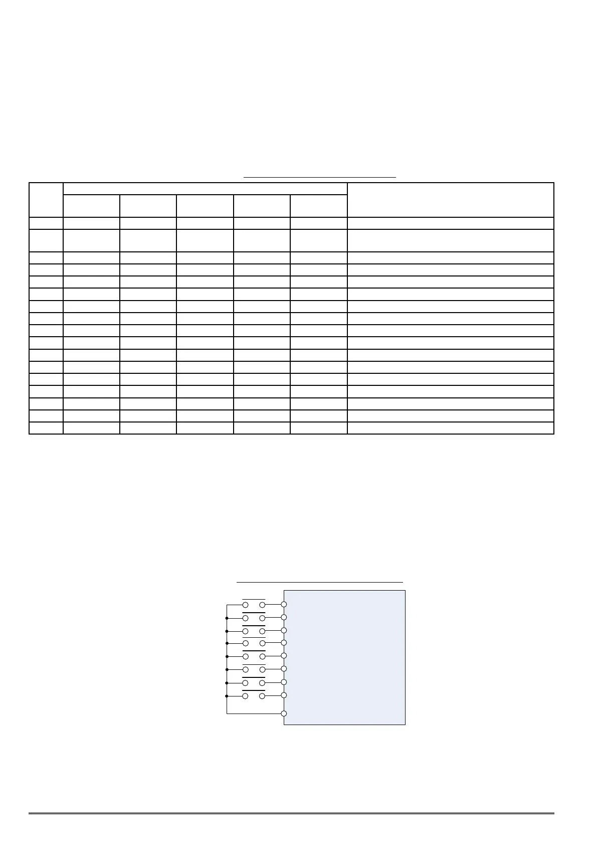
WiringExample: Figure 4.4.17 and 4.4.18 show an example of a 9-speed operation selection.
Figure4.4.17ControlTerminalWiringExample
S1 Forward Run / Stop (03-00 = 0)
S2 Reverse Run / Stop (03-01 = 1)
24VG
S3 External Fault (03-02 = 25)
S4 Fault Reset (03-03 = 17)
S5 Multi-Step Speed Ref 1 (03-04=2)
S6 Multi-Step Speed Ref 2 (03-05=3)
S7 Multi-Step Speed Ref 3 (03-06=4)
S8 Jog Frequency Reference (03-07=29)
146 VDI100 • Instruction manual

 Loading...


