Figure4.4.109ASRblockdiagram(SVmode)
20-00
20-02
20-01
20-03
20-08
Frequency
Reference
Speed
Feedback
I Limit
20-04
Primary
delay time
Torque
Limit
Torque
Reference
21-05 to 21-08
20-07 = 1 (during
accel/decel)
20-07 = 0
Speed Control Integral
reset
03-00 to 03-07 = 43
P
I
+
-
+
+
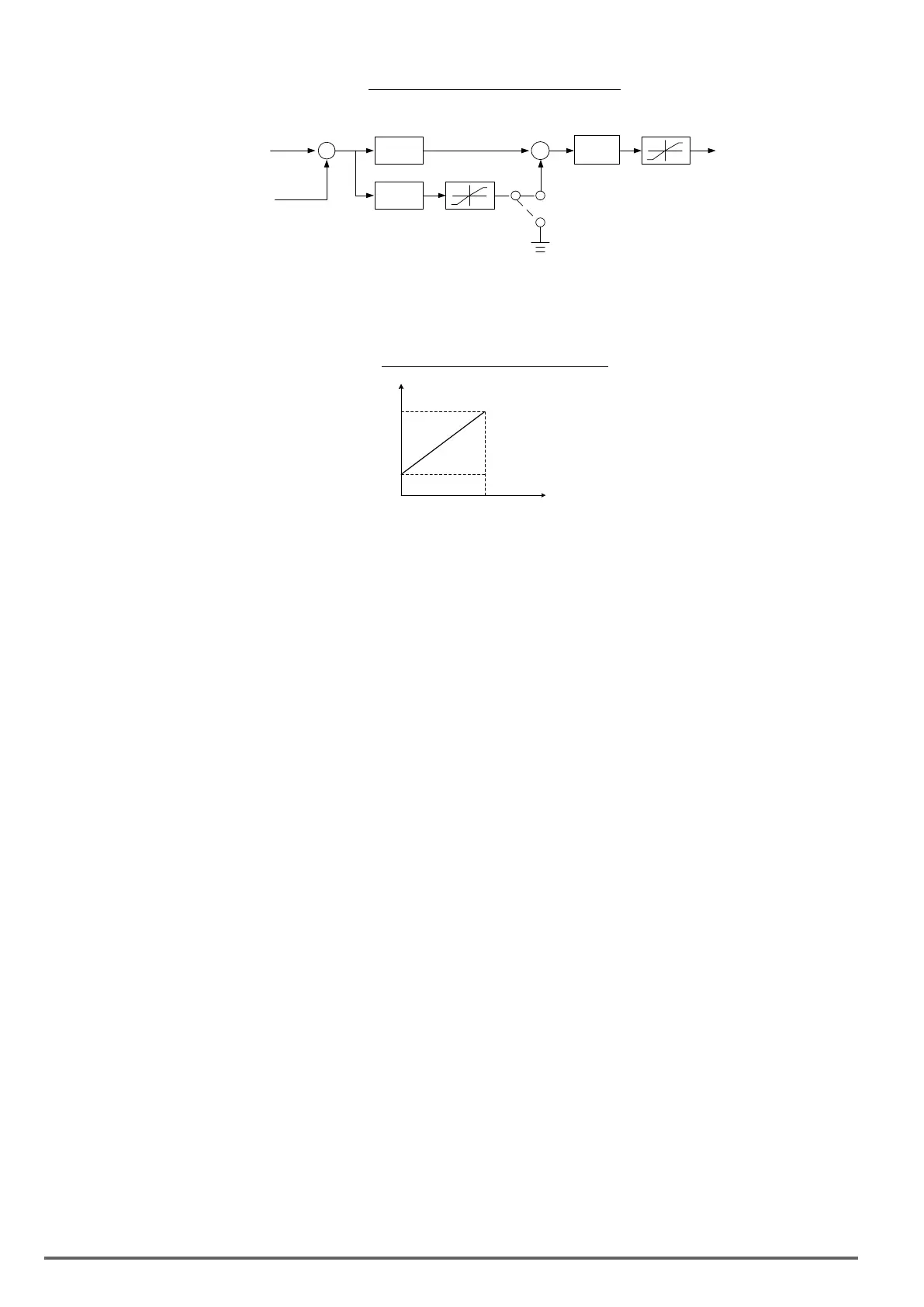
ASRsettinginV/f+PGcontrolmode
In V/f+PG mode, set the proportional (P) gain and integral (I) time at the minimum output frequency (20-02 and
20-03) and maximum output frequency (20-00 and 20-01). Refer to the gure 4.4.110.
Figure4.4.110ASRgainsetting(V/f+PG)
P.I
0%
100%
(Fmax , 01-02)
P=20-00
I=20-01
P=20-02
I=20-03
Output
Frequency
Tuning the speed control ASR gain:
a) ASR gain tuning at minimum output frequency
1. Operate the motor at the lowest output frequency.
2. Increase the ASR proportional gain 2 (20-02) as much as possible without causing instability.
3. Decrease the ASR integral time 2(20-03) as much as possible without causing instability.
4. Check that the output current is less than 50% of the inverter rated current.
If the output current is more than 50% of the inverter rated current, decrease 20-02 and increase 20-03.
b) ASR gain tuning at maximum output frequency
1. Operate the motor at the highest output frequency (Fmax).
2. Increase the ASR proportional gain 1 (20-00) as much as possible without causing instability.
3. Decrease the ASR integral time 1(20-01) as much as possible without causing instability.
c) The gain tuning of acceleration / deceleration integral control (20-07)
1. To enable during acceleration / deceleration operation set 20-07 = 1 (enabled), the integral control is ena-
bled.
2. Integral control enables the motor speed to reach its target speed as soon as possible, but it may result in
over or undershoot, as shown in Figure 4.4.113 & 4.4.114.
3. When one of multi-function digital inputs (03-00 to 03-07) is set to 43 (speed control integral reset), the input
can be used to switch between P control and PI control of the speed control loop system (ASR). When the
multi-function digital input is on, only P control is active and the integral is reset.
a. If the speed overshoot occurs, reduce 20-00 system (ASR proportional gain) and increase the 20-01
system (ASR integral time 1).
b. If the desired speed is not reached, reduce 20-02 system (ASR proportional gain 2) and increase 20-03
(ASR integral time 2).
c. If you cannot eliminate the speed over or undershoot using the gain tuning described above, decrease
the ASR + / - limit (20-05 / 20-06), to decrease the reference frequency compensation (Δf) limit. Since 20-
05/20-06 cannot be changed during running, it is necessary to stop the inverter rst and then decrease the
ASR + / - limit.
4. See gure 4.4.111, observe the motor speed waveform and tune the gain at the same time.
264 VDI100 • Instruction manual

 Loading...


