Figure4.4.111Analogoutputsetting
AO1
AO2
Related Parameters
04- 11 = 6 (Motor Speed)
04- 12 (Gain)
04- 13 (Bias)
{
04-16 = 6 (Motor Speed)
04- 17 (Gain)
04- 18 (Bias)
{
d) ASR+/-limit (20-05, 20-06)
ASR +/-limit is ASR frequency compensation limit and is set as a percentage of the maximum frequency
output 01-02.
Note: If the frequency limit is set too low, the actual motor speed may not reach the target speed.
ASRsetting(SV/SLV/PMSVcontrolmode)
In SLV mode the ASR gain is divided into a high-speed and low-speed section. The speed controller has a
high-speed gain 20-00/20-01 and a low-speed gain 20-02/20-03 that can be set independently.
a) The high/low switch frequency can be set with parameter 20-15 and 20-16. Similar to the ASR gain, the
speed estimator has a high-speed gain 20-09/20-10 and a low-speed gain 20-11/20-12.
b) The speed estimator has a low-pass lter to reduce the speed feedback interference, parameter 20-13 and
20-14 are active at high speed as well as low speed. The switch between the high-speed and the low-speed
is set by parameter 20-15 and 20-16.
c) 20-17 sets the low-speed compensation gain of the speed feedback.
d) 20-18 sets the high-speed compensation gain of the speed feedback.
e) When the frequency reference is rises above the value set in 20-16, the ASR gain used is set by parame-
ters 20-00 and 20-01.
f) When the frequency reference falls below the value set in 20-15, the ASR gain used is set by parameters
20-02 and 20-03.
g) Gain time constant is adjusted linearly when the speed command falls within the range of 20-15 to 20-16,
for a smooth operation.
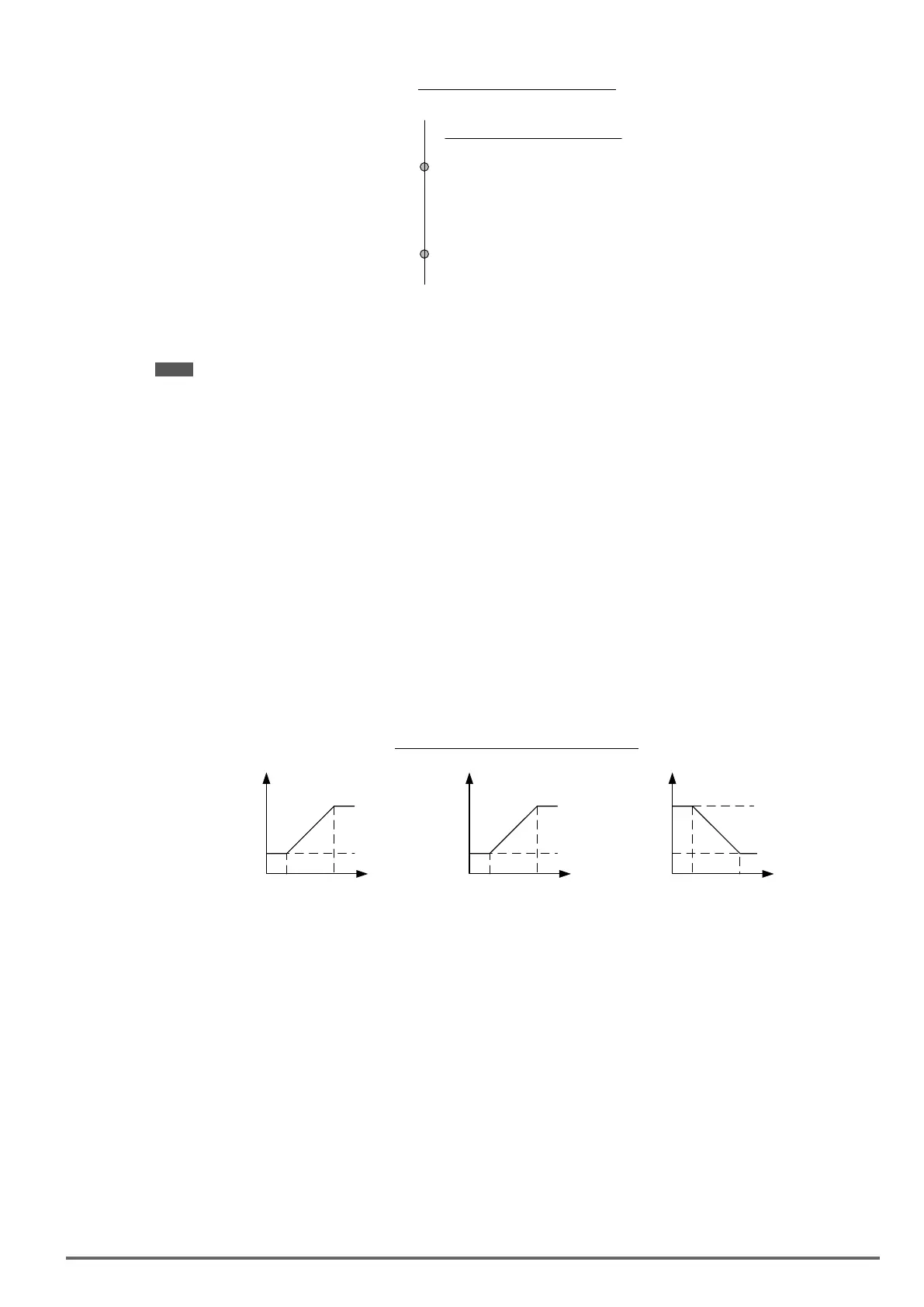
Figure4.4.112ASRgainsetting(SLVmode)
P,I P,I
20-15
20-15 20-15
20-16
20-16 20-16
P = 20-00
I = 20-01
P = 20-00
I = 20-01
P = 20-02
I = 20-03
Frequency
Reference
Frequency
Reference
20-13
20-14
Time
Constant
SV and PMSV gain setting
In SV and PMSV mode the ASR gain is divided into a high-speed and low-speed section. The speed controller
has a high-speed gain 20-00/20-01 and a low-speed gain 20-02/20-03 that can be set independently.
Tune the speed control gain
During ASR gain tuning, the multi-function analog output (AO1 and AO2 terminal) can be used to monitor the
output frequency and motor speed (as shown in gure 4.4.112). Use parameters 20-00 ~ 20-03 for full speed
range gain tuning in SV and PMSV mode.
a) Complete the parameter tuning in normal operation.
b) Increase ASR proportional gain 1 (20-00), ASR proportional gain 2 (20-02), carefully monitor system stabili-
ty.
Use parameter 20-00 and 20-02 to adjust the speed response for each cycle. Tuning the settings of 20-00, 20-
02 can increase system response, but may cause system instability. See gure 4.4.113.
VDI100 • Instruction manual 265

 Loading...


