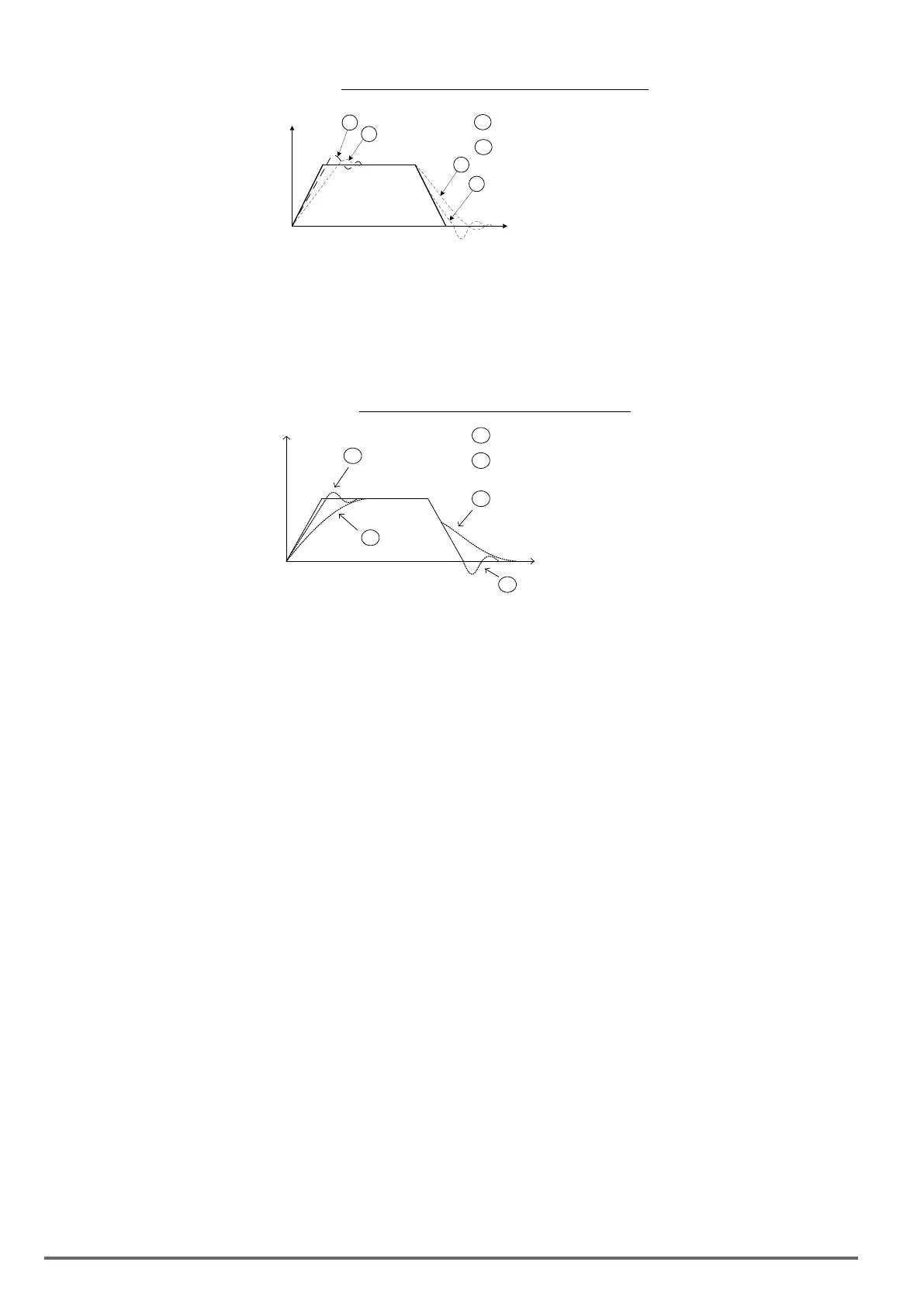
Figure4.4.113SystemresponseofASRproportiongain
1
1
2
2
t
Speed
1
:20-00 setting is too high(oscillation occurs)
2
:20-00 setting is too low(slow response)
a) Reduce ASR integral time 1(20-01), ASR integral time 2 (20-02) and carefully monitor system stability.
1. A long integral time will result in poor system response.
2. If the integral time setting is too short, the system may become unstable Refer to the following gure.
While tuning ASR P and I gain the system may overshoot and an over voltage condition can occur. A braking
unit (braking resistor) can be used to avoid an over voltage condition.
Figure4.4.114TheresponseofASRintegraltime
1
1
2
2
t
Speed
1
: 20-01 setting is too short(oscillation occurs)
2
: 20-01 setting is too long(slow response)
SLV mode gain tuning (20-00~20-03, 20-09~20-18) and SLV2 mode gain tuning (20-15, 20-16)
Tune the low-speed ASR P and I gain 20-02 ~ 20-03, make sure the reference frequency is below the value of
parameter 20-15. P gain and integral time tuning is the same as for parameter 20-00 and 20-01 in SV mode.
Tune the high-speed ASR PI gain 20-00~20-01, make sure the reference frequency is above parameter 20-16
value. P gain and integral time tuning is the same as for parameter 20-00 and 20-01 under SV mode.
Both low-speed ASR gain and the high-speed gain can be set to the same values and only require to be adjust-
ed in case of system instability.
In case tuning of the ASR P and I gain 20-00~20-03 does not improve the system response, reduce the low-
pass lter time constant 20-13~20-14 to increase the bandwidth of the feedback system and re-tune the ASR
gain.
• Tune low-speed low-pass lter time constant 20-14, make sure the reference frequency is below parameter
20-15 value
• Tune high-speed low-pass lter time constant 20-13 at frequency reference, make sure the reference fre-
quency is above parameter 20-16 value.
• Increasing the low-pass lter time constant can limit the bandwidth of the speed feedback system and may
reduce the system response. Increasing the low-pass time reduces the speed feedback signal interference
but may results in sluggish system response when the load suddenly changes. Adjust the low-pass lter
time if the load stays fairly constant during normal operation. The low bandwidth of the speed feedback
must be supported by the low gain of ASR to ensure the stable operation.
• Decreasing the low-pass lter time constant may increase the bandwidth of the speed feedback and the
system response. Decreasing the low-pass time may increase the speed feedback interference resulting
in system instability when the load suddenly changes. Decrease the low-pass lter time is a quick system
response is required for rapidly changing loads. The high bandwidth of the speed feedback allows for a
relative high ASR gain.
• In case tuning 20-00 ~ 20-03 and the low-pass lter time constant 20-13 do not improve the system re-
sponse time, tuning the PI gain 20-09 ~ 20-12 of the speed estimator may be required.
• Setting a high gain for the speed estimator (high proportion (P) gain and small integral (I) time) increases
the bandwidth of the speed feedback, but may cause speed feedback interference resulting in system
instability.
• Setting a low gain for the speed estimator (small proportion (P) gain and high integral (I) time) decreases
the bandwidth of the speed feedback, may improve speed feedback interference resulting in a more stable
system.
266 VDI100 • Instruction manual

 Loading...


