Code Parameter Name / Range
21-28 The command of rotation cycle number of section 9
-9999~9999
21-29 The command of the pulse number of section 9
-9999~9999
21-30 The command of rotation cycle number of section 10
-9999~9999
21-31 The command of the pulse number of section 10
-9999~9999
21-32 The command of rotation cycle number of section 11
-9999~9999
21-33 The command of the pulse number of section 11
-9999~9999
21-34 The command of rotation cycle number of section 12
-9999~9999
21-35 The command of the pulse number of section 12
-9999~9999
21-36 The command of rotation cycle number of section 13
-9999~9999
21-37 The command of the pulse number of section 13
-9999~9999
21-38 The command of rotation cycle number of section 14
-9999~9999
21-39 The command of the pulse number of section 14
-9999~9999
21-40 The command of rotation cycle number of section 15
-9999~9999
21-41 The command of the pulse number of section 15
-9999~9999
21-42 Pos. Mode Sel
0: Switch to position mode when output frequency < 01-08.
1: Z Phase Locked Function
21-43 Offset Angle
0 ~9999 Pulse
21-09 Maximum frequency for position control
Maximum output frequency when moving to the next position. The position control function uses
aceleration
time 1 (00-14) / deceleration time 1 (00-15).
In the SV control mode, multi-function digital input terminals (03-00 to 03-07) can be used to select the position.
See table 4.4.19.
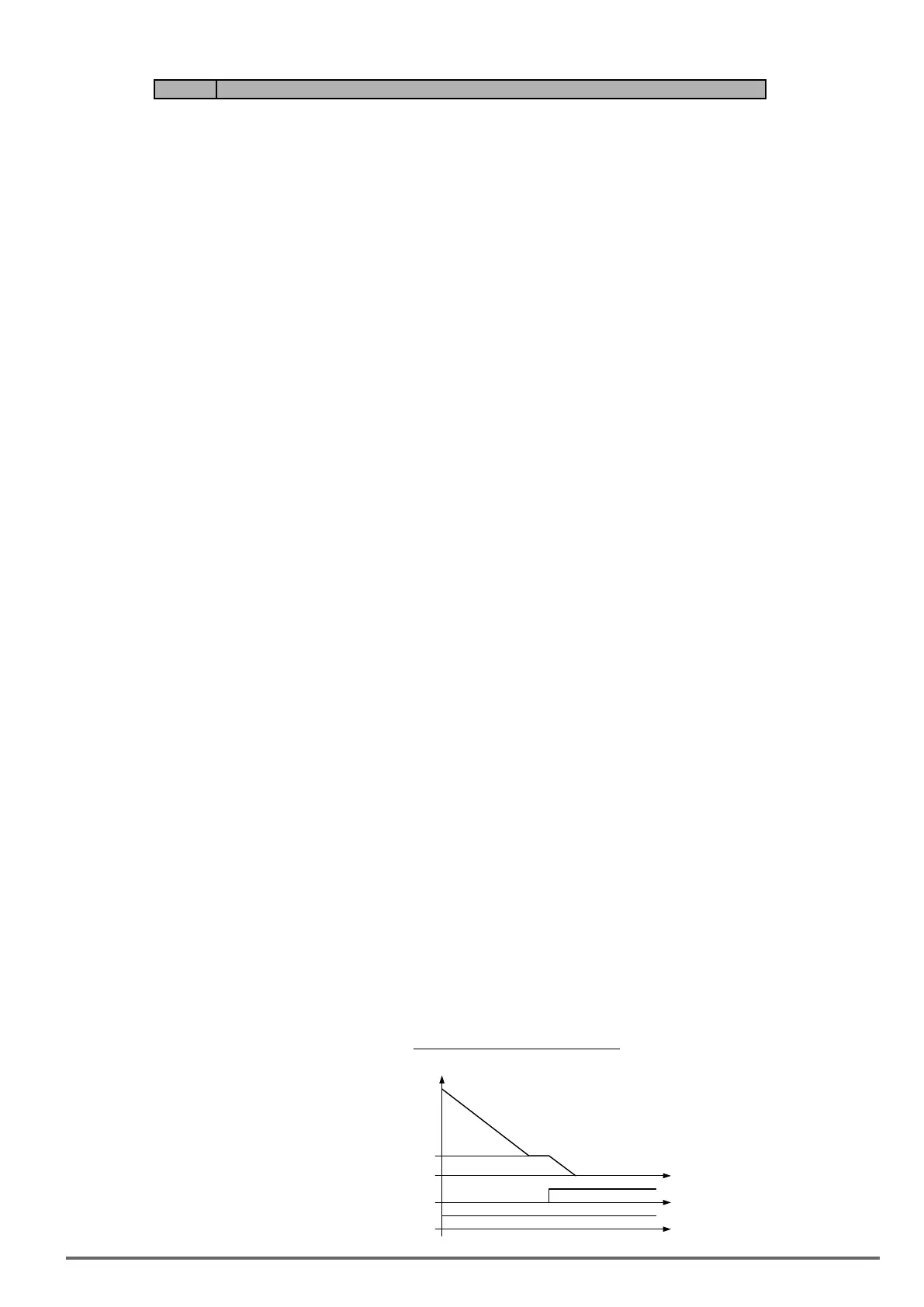
Figure4.3.129Zero-servopositioning
Run
DI (Zero Servo)
Fmin (01-08)
Output
VDI100 • Instruction manual 277

 Loading...


