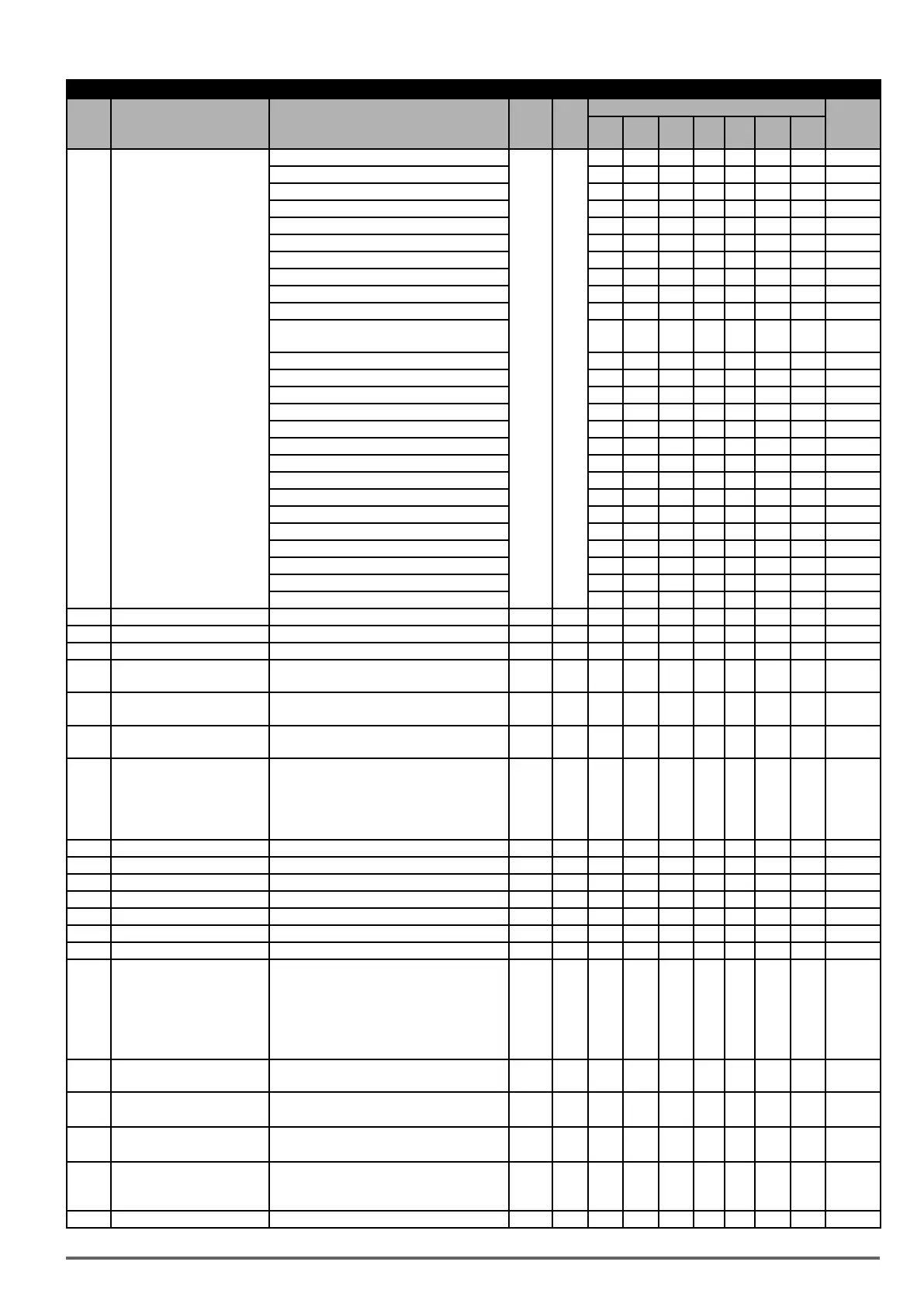
Group 03: External Digital Input and Output Parameters
Code Parameter Name Setting Range Default Unit
Control mode
Attribute
V/f
V/f
+PG
SLV SV
PM
SV
PM
SLV
SLV2
29 : During Traverse Operation Status O O X X X X O
30 : Motor 2 Selection O O O O O O O
31: Zero Speed Servo Status (Position Mode) X X X O O X X
32: Communication Control Contacts O O O O O O O
33: Reserved - - - - - - -
34: Reserved - - - - - - -
35: Reserved - - - - - - -
36: Reserved - - - - - - -
37: PID Feedback Loss Detection Output O O O O O O O
38: Brake Release X X O O O X X
39: Frequency Detection 1 (dedicated for
Crane)
O O O X X X X
40: Frequency Output O O O O O X X
41: Position Agree (Position Mode) O O O O O X X
42: Reserved - - - - - - -
43: Reserved - - - - - - -
44: Reserved - - - - - - -
45: PID sleep O O O O O O O
46: Reserved - - - - - - -
47: Reserved - - - - - - -
48: Reserved - - - - - - -
49: Reserved - - - - - - -
50: Frequency Detection 3 (> 03-44+03-45) O O O O O O O
51: Frequency Detection 4 (< 03-44+03-45) O O O O O O O
52: Frequency Detection 5 (> 03-46+03-47) O O O O O O O
53: Frequency Detection 6 (< 03-46+03-47) O O O O O O O
54: Turn on short-circuit braking X X X X X O X
03-13 Frequency Detection Level 0.0~599.0 0.0 Hz O O O O O O O
03-14 Frequency Detection Width 0.1~25.5 2.0 Hz O O O O O O O
03-15 Current Agree Level 0.1~999.9 0.1 A O O O O O O O
03-16
Delay Time of Current Agree
Detection
0.1~10.0 0.1 s O O O O O O O
03-17
**Mechanical Braking Rele-
ase Level
0.00~599.00 0.00 Hz O O O O O O O
03-18
**Mechanical Braking Level
Set
0.00~599.00 0.00 Hz O O O O O O O
03-19 Relay (R1A-R2A) Type
xxx0b: R1 A Contact
xxx1b: R1 B Contact
0000b - O O O O O O O
xx0xb: R2 A Contact
(DO2 for F1)
xx1xb: R2 C Contact
03-20 Reserved
03-21 Reserved
03-22 Reserved
03-23 Reserved
03-24 Reserved
03-25 Reserved
03-26 Reserved
03-27
UP/DOWN Frequency Hold/
Adjust Selection
0: Hold last set frequency when stopped 0 - O O O O O O O
1: Set frequency to 0 when stopped
2: Allow speed changes from last set frequen-
cy when stopped
3: Refresh frequency at acceleration.
03-28 Photo-coupler Output
Range and definition are the same as those of
03-11, 03-12
0 - O O O O O O O
03-29
Photo-coupler Output
Selection
xxx0b: Photo-coupler A Contact
0000b - O O O O O O O
xxx1b: Photo-coupler B Contact
03-30 Selection of Pulse Input
0: General Pulse Input
0 - O O O O O O O
1: PWM
03-31 Scale of Pulse Input
Depending on the setting of 03-30
03-30 = 0: 50~32000Hz
03-30 = 1:10~1000Hz
1000 Hz O O
O O O O O *1
03-32 Pulse Input Gain 0.0~1000.0 100 % O O O O O O O *1
VDI100 • Instruction manual 63

 Loading...


