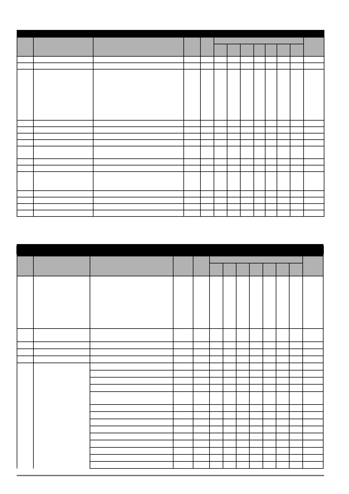
Group 03: External Digital Input and Output Parameters
Code Parameter Name Setting Range Default Unit
Control mode
Attribute
V/f
V/f
+PG
SLV SV
PM
SV
PM
SLV
SLV2
03-33 Pulse Input Bias -100.0~100.0 0.0 % O O O O O O O *1
03-34 Filter Time of Pulse Input 0.00~2.00 0.1 s O O O O O O O *1
03-35
Function Setting of Pulse
Output
1: Frequency Command 2 - O O O O O O O *1
2: Output Frequency
3: Output Frequency after Soft-Start
4: Motor Speed
5: PID Feedback
6: PID Input
7: PG Output (with PG card)
03-36 Scale of Pulse Output 1~32000 1000 Hz O O O O O O O *1
03-37 Timer ON Delay (DIO) 0.0~6000.0 0.0 s O O O O O O O
03-38 Timer OFF Delay (DIO) 0.0~6000.0 0.0 s O O O O O O O
03-39 Reserved
03-40
Up/Down Frequency Width
Setting
0.00~5.00 0.00 Hz O O O O O O O
03-41 Torque Detection Level 0~300 10 % X X O O O X X
03-42 Brake Release Delay Time 0.00~65.00 0.00 s X X O O O X X
03-43
UP/DOWN Acceleration/
Deceleration Selection
0: Acceleration/ Deceleration Time 1
0 - O O O O O O O
1: Acceleration/ Deceleration Time 2
03-44 Frequency Detection Level 2 0.0~599.0 0.0 Hz O O O O O O O
03-45 Frequency Detection Width 2 0.1~25.5 2.0 Hz O O O O O O O
03-46 Frequency Detection Level 3 0.0~599.0 0.0 Hz O O O O O O O
03-47 Frequency Detection Width 3 0.1~25.5 2.0 Hz O O O O O O O
* 2-wire operation mode: 29; 3-wire operation mode: 26.
* *If the maximum output frequency of motor is over 300HZ,the frequency resolution is changed to 0.1Hz
Group 04: External Analog Input and Output Parameters
Code Parameter Name Setting Range Default Unit
Control mode
Attribute
V/f
V/f
+PG
SLV SV
PM
SV
PM
SLV
SLV2
04-00 AI Input Signal Type
0: AI1:0~10V
AI2: 0~10V / 0~20mA
1 - O O O O O O O
1: AI1:0~10V
AI2: 4~20mA/ 2~10V
2: AI1: -10~10V
AI2: 0~10V/ 0~20mA
3: AI1: -10~10V
AI2: 4~20mA/ 2~10V
04-01
AI1 Signal Scanning and
Filtering Time
0.00~2.00 0.03 s O O O O O O O
04-02 AI1 Gain 0.0~1000.0 100.0 % O O O O O O O *1
04-03 AI1 Bias -100.0~100.0 0 % O O O O O O O *1
04-04 Reserved
04-05 AI2 Function Setting 0: Auxiliary Frequency 0 - O O O O O O O
1: Frequency Reference Gain O O O O O O O
2: Frequency Reference Bias O O O O O O O
3: Output Voltage Bias O O X X O O O
4: Coefficient of Acceleration and Decele-
ration Reduction
O O O O O O O
5: DC Braking Current O O O O X X O
6: Over-Torque Detection Level O O O O O O O
7: Stall Prevention Level During Running O O X X X X O
8: Frequency Lower Limit O O O O O O O
9: Jump Frequency 4 O O O O O O O
10: Added to AI1 O O O O O O O
11: Positive torque limit X X O O O O X
12: Negative torque limit X X O O O O X
13: Regenerative Torque Limit X X O O O O X
64 VDI100 • Instruction manual

 Loading...


