T",BAR
CONTROLLED
LOADERS
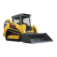
(Fig.
2)
Side-mounted T
-Bars
are provided on Skid Loader
to
control the hydraulic and hydrostatic functions
of
the Loader.
Both T-Bars return to their "neutral" positions when released.
PROPULSION CONTROL
T-BAR
The left T-Bar
is
the Propulsion Control which is
linked to the Hydrostatic Drives.
Forward
Travel:
Push the left T-Bar straight forward
(without twisting).
Reverse
Travel:
Pull the left
T-
Bar straight backwards
(without twisting).
Turning
during
Travel:
Twist the left T-Bar and move
it slightly forward or rearward to cause a slow gradual
forward or rearward turn. The farther the T-Bar
is
moved, in any direction, the faster the maneuver will
be made. Engine RPM also has a directly proportional
affect on movement.
Fast
Turning
(Pivoting):
Twist
the
left
T-Bar
clockwise to cause a spin turn to the right; twist the
T-Bar counterclockwise
to
cause a spin turn to the left.
On a spin turn, the wheels opposite the direction
of
the
turn will rotate forward and the wheels on the same
side as the direction
of
the turn will rotate rearward.
CAUTI
N
ALWAYS
make
sure
that
both
T-Bars
are
in
their
"neutral"
positions
BEFORE
attempting
to
start
the
Engine.
Operation
of
the
T-Bar
controls
should
be
smooth
and
with
safety
in
mind.
Excessive
travel
speed
together
with
quick
T-Bar
movements,
with
NO
regard
for
conditions
and
circumstances,
is
hazardous
and
could
cause
an
accident.
Lift/Tilt
Control
T-Bar
The
right T-Bar controls the Lift (Arm) and Tilt
(Attachment) through linkage to the Loader's Main
Hydraulic Control Valve.
Attachment
Travel:
Twist the right T-Bar clockwise
to
tilt
the
Attachment
downward;
twist
it
counterclockwise to tilt the Attachment up
or
back.
-"llll~-
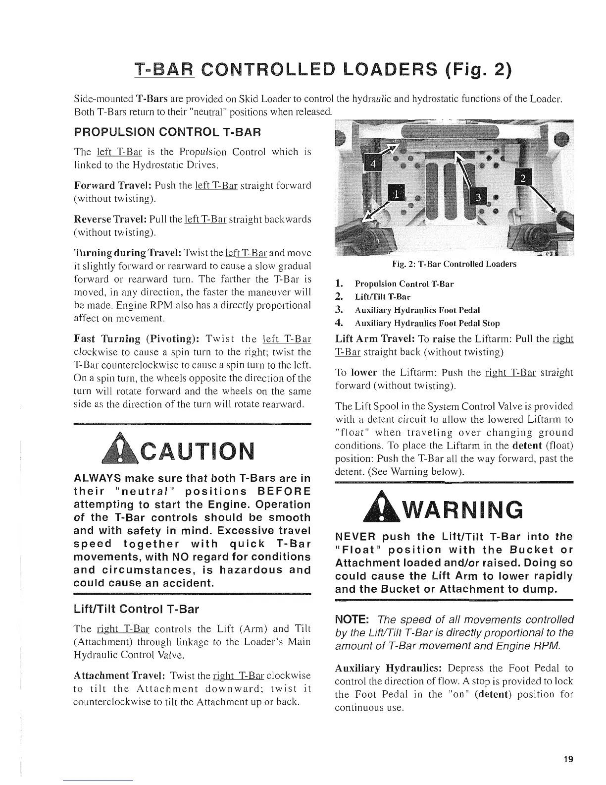
Fig.
2:
T-Bar Controlled Loaders
1. Propulsion Control T-Bar
2.
Lift/Tilt T-Bar
3. Auxiliary Hydraulics Foot Pedal
4. Auxiliary Hydraulics Foot Pedal Stop
Lift
Arm
Travel:
To
raise
the Liftarm: Pull the right
T-Bar straight back (without twisting)
To
lower
the Liftarm: Push the right T-Bar straight
forward (without twisting).
The Lift Spool in the System Control Valve is provided
with a detent circuit to allow the lowered Liftarm to
"float"
when
traveling
over
changing
ground
conditions. To place the Liftarm in the
detent
(float)
position: Push the T-Bar all the way forward, past the
detent. (See Warning beloW).
WARNING
NEVER
push
the
Lift/Tilt
T-Bar
into
the
"Float"
position
with
the
Bucket
or
Attachment
loaded
and/or
raised.
Doing
so
could
cause
the
Lift
Arm
to
lower
rapidly
and
the
Bucket
or
Attachment
to
dump.
NOTE:
The speed
of
aI/ movements control/ed
by
the LiftlTilt T-Bar is directly proportional
to
the
amount
of
T-Bar movement and Engine RPM.
Auxiliary
Hydraulics:
Depress the Foot Pedal to
control the direction
of
flow. A stop is provided to lock
the
Foot
Pedal
in the "on"
(detent)
position
for
continuous use.
19
 Loading...