DRIVE CHAINS (Fig. 31)
Drive Chains should be checked and adjusted after every
100 hours
of
operation.
To
properly adjust the Drive
Chain Tension on either side
of
the Loader, follow the
directions below.
1.
Raise the Loader
off
the ground following the
"Loader Raising Procedure" topic at the beginning
of
this chapter.
2.
Remove the Access Cover at the outside, center
of
the Chaincase (between the Wheels) to gain access to
the Drive Chain Front and Rear Take-up Assemblies.
3.
Rotate the Front and Rear Tires (by hand) towards
each other so that the slack sides
of
the Chains are at
the top.
4.
Working through the access hole, loosen the Jam Nut
and Lock Nut, and then tighten the Adjustment Nut
on either
of
the two Chains. This will cause the Idler
Assembly to lower and thereby increase tension on
the Chain.
5.
Correct Chain deflections
is
114"
@ 20
Ibs.
on the side
opposite from the Adjuster -
112
way between the
Sprockets. (see Fig. 31).
2
1
3
6.
If it
is
not possible to measure deflection, adjust the
Chain as follows: have an assistant attempt to turn the
Tire back and forth while you tighten the Adjustment
Nut. When
it's
no longer possible to turn the Tire by
hand, the Chain
is
tight enough for Loader operation.
7.
After the proper Chain tension is obtained, retighten
the Jam Nut and Lock Nut.
NOTE:
Overtightening
the Drive Chain will
cause premature Drive Chain
and
Axle Sprocket
wear.
8.
Repeat steps 4 through 5 for the other Chain.
9.
Repeat steps 2 through 6 for the other side
of
Loader.
10.
If
necessary, Replenish the Chaincase oil level to
1
112"
deep as measured directly below Access open-
ing. (see Fig. 31) Then, reinstall both Chaincase
Access Covers using oil resistant RTV or equivalent
between the Cover and the Chaincase.
11.
Follow "Loader Lowering Procedure" topic at the
beginning
of
this chapter to return Loader to the
ground.
2
II
II
II
II
======='11
II
II
II
II
II
II
II
4
1/4"
Chain
Deflection;\
II
/
~
II
II
_---L-_-_--;
0_
0 h 0 0
::
5
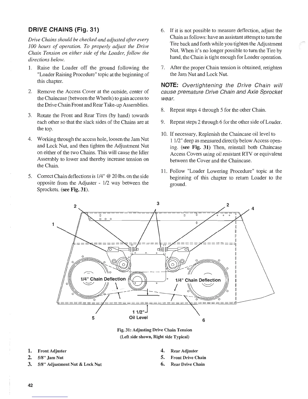
1. Front Adjuster
2. 5/8"
Jam
Nut
3. 5/8" Adjustment Nut & Lock Nut
42
11/2"
Oil
Level
==================::!
6
Fig. 31: Adjusting Drive Chain Tension
(Left side shown, Right side Typical)
4. Rear Adjuster
5. Front Drive Chain
6.
Rear Drive Chain
 Loading...