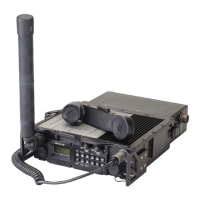
General Dynamics C4 Systems URC-200 (V2)
20
With the ball and swivel joint free to swivel, screw the antenna to the ANT connector using only
the collar ring. Exercise extreme care to prevent the threads on the collar ring from cross-threading
with the threads on the ANT connector.
Set the antenna to desired position and tighten the swivel joint clamp ring against the collar ring.
Once the swivel joint clamp ring is tightened, DO NOT use the antenna as a lever to cinch the
collar ring to the ANT connector.
CAUTION
Several conditions must be observed when using the UVU-100 LOS antenna
mounted on the transceiver's front panel, as serious damage to the transceiver
may result if high RF power is allowed to leak into the interior of the transceiver
directly from the antenna.
1. Transmit ONLY with the cover of the transceiver securely fastened in place.
2. Use ONLY vendor supplied power supplies, such as the RF shielded battery
case (UBC-100) or power supply (UAC-100).
3. Use ONLY tempest approved shielded cables with the REMOTE connector.
CAUTION
To comply with RF exposure requirements, a minimum separation distance of
20 cm (7.9 inches) is required between the antenna and all persons while the
transceiver is transmitting. ManPack (backpack) and hand-carry users should
not exceed 50% duty cycle, as this approaches RF hazard limits and reduces
battery life.
2.2.3 Removing the Antenna
To remove the antenna from the transceiver, loosen the swivel clamp ring to allow the ball and
swivel joint, at the antenna’s mounting base, to freely swivel. Then unscrew the collar ring from the
ANT connector and remove the antenna. With the swivel joint clamp ring tightened, DO NOT use
the antenna as a lever to loosen or remove the collar ring from the ANT connector.
2.2.4 Transceiver Placement and Antenna Sighting
The transceiver operates in the VHF and UHF frequency bands, and so uses Line-Of-Sight (LOS)
frequencies. Therefore, placement of the transceiver and antenna sighting greatly affects operating
range. The longest range is normally obtained when a direct LOS is maintained between the
transceivers. Use of hilltop or tower locations will increase the LOS range. Location in valleys with
intervening hills, behind buildings or in dense woods may reduce or prevent communications. If
possible, avoid locations near electrical interference sources, such as power and telephone lines,
radars, welders and electrical generators.

 Loading...