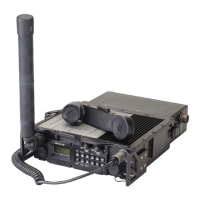
General Dynamics C4 Systems URC-200 (V2)
122
Table 26 - Power Connector J5 (CA110821-1) Pin Characteristics
PIN FUNCTION
12V Battery 1 - Negative / Transceiver Ground for External Power Source
12V Battery 2 - Negative (Tied to Pin 4 internal to the Transceiver)
3 Rechargeable battery sense. No Connection for non-rechargeable battery.
Grounded for rechargeable battery.
12V Battery 1 - Positive (Tied to Pin 2 internal to the Transceiver)
5 12V Battery 2 - Positive / +24 V transceiver power from External Power
Table 27 - Handset Connector J4 (GC283F-1-050) Pin Characteristics
PIN
FUNCTION
PT OUT. Adjustable from 0V to 11.5 V Peak at full modulation into 600
Ω
PTT-N. Push-to-Talk. Ground to Transmit
PT IN. 1-200 mVrms nominal into 150
Ω
Connected to pin B. (See Pin B)
Squelch. Receiver Squelch Output for RETRANSMIT, 0 TO +5V, logic gate
output with a 100
Ω
series resistor. +5V = Squelched. 0V = Not squelched.

 Loading...