General Dynamics C4 Systems URC-200 (V2)
25
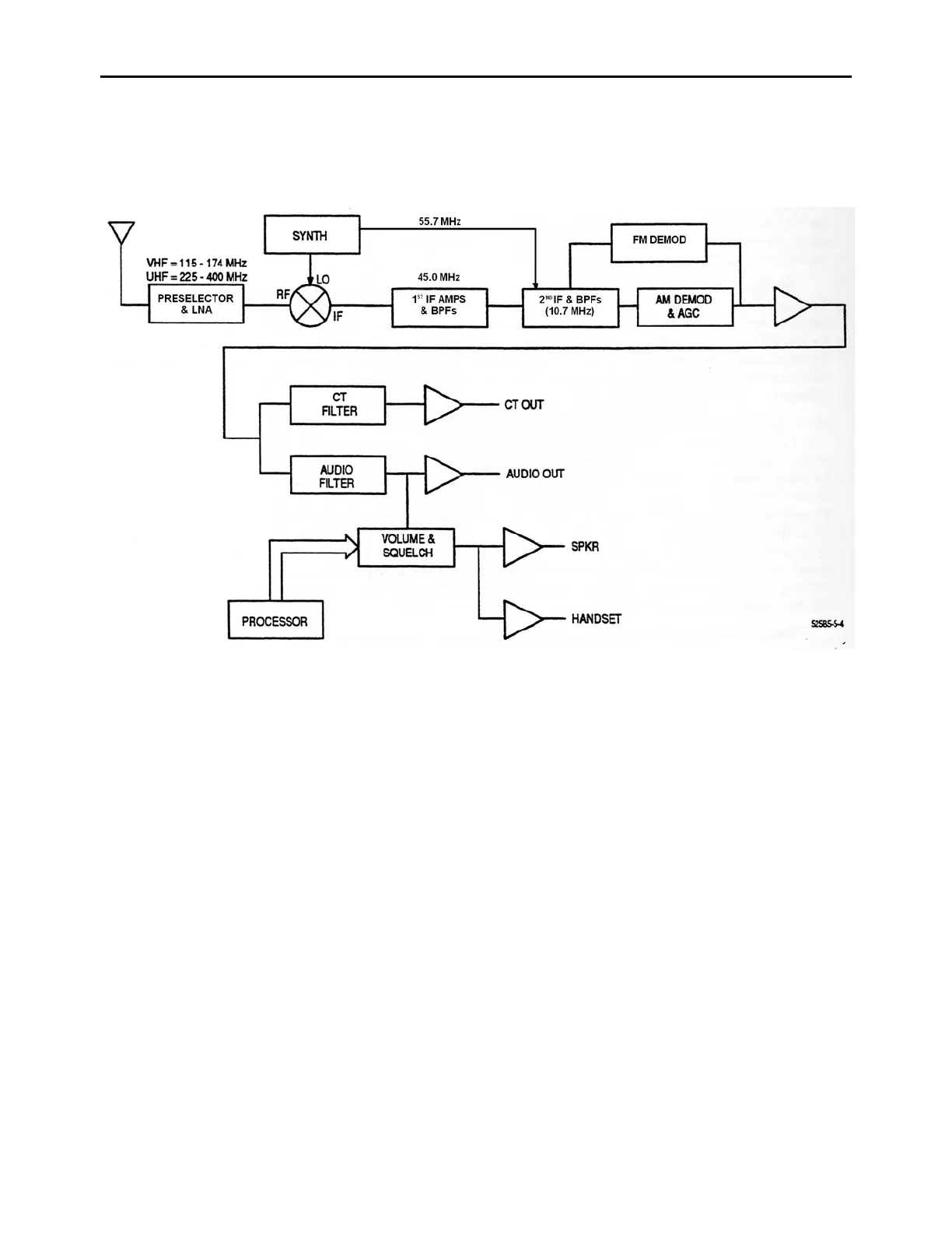
amplified and routed to the remote connector on the front panel. For PT operation, the audio signal
is amplified and routed to the remote connector, the speaker, and the handset.
Figure 6 - Receiver Functional Block Diagram
Volume and Squelch control signals are provided by the processor to control the volume and
squelch settings of the audio circuitry. The Processor receives the volume setting from the front
panel control and uses this setting to set the volume controls in the audio circuitry. For squelch
operation, the processor also receives a squelch setting from the front panel control and uses this
setting to compare against the received signal strength and noise level to activate the squelch
controls. The received signal strength level is provided by the AGC circuitry, which provides a
direct indication of relative signal strength. The noise level is measured by coupling the
demodulated FM signal through a high-pass filter and a peak detector to provide an indication of
relative noise level. The signal-to-noise ratio is compared against the squelch control setting to
determine if the squelch threshold is broken.
3.2.1 Receiver Input Signals
Figure 7 shows input and output signals of the receiver. The RF IN signal is the received signal
routed from the receiver. The RF IN signal may be either VHF (115 to 149.9950 MHz [AM] or
173.9950 MHz [FM]) or UHF (225 to 399.9950 MHz) signal in either FM or AM mode of
modulation. (It may also be an extended UHF [400-420 MHz] signal in FM mode for the 400 MHz
option.) The LO signal is provided by the synthesizer and is set at 45.0 MHz above the desired
received signal. (Low-side mixing is used for 400-420 MHz band, therefore, data output in this