General Dynamics C4 Systems URC-200 (V2)
34
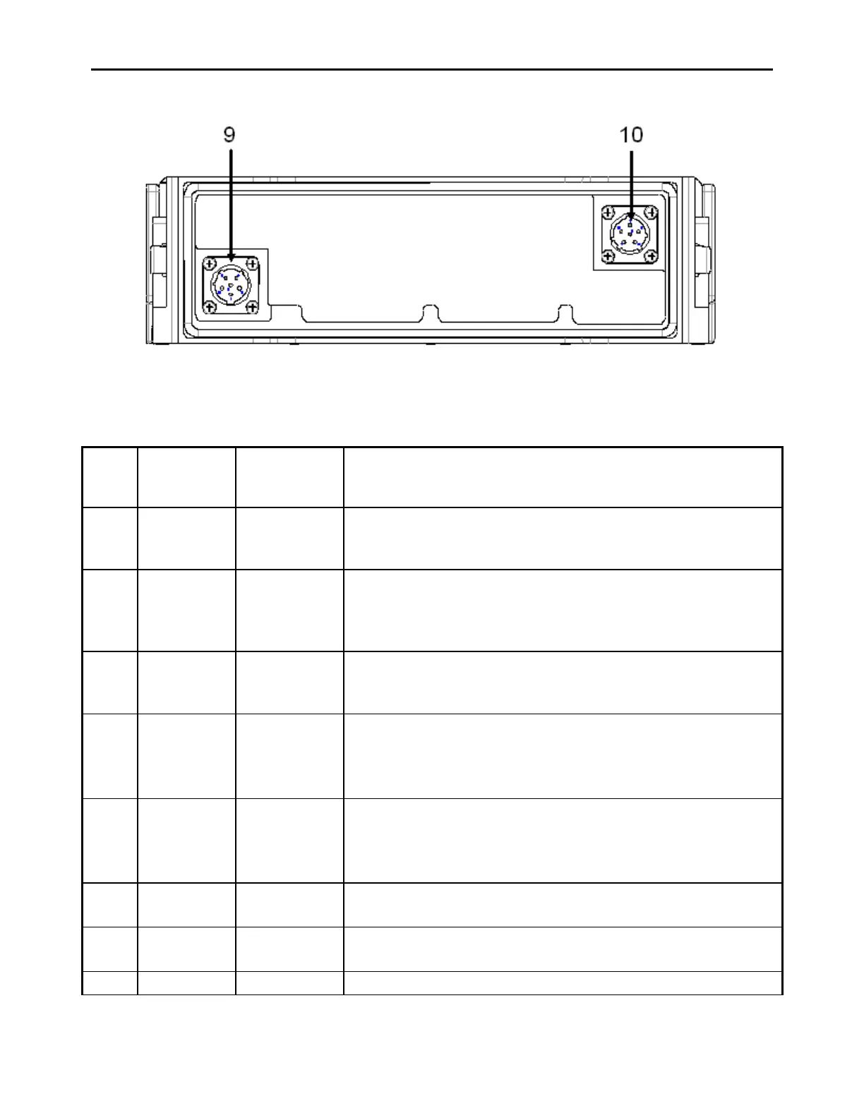
Figure 11 - Front and Rear Panel Controls, Indicators and Connectors
Table 7 - Front Panel Controls, Indicators and Connector and Rear Panel Connectors
Item
No.
Indicators,
Connectors
Type Function
1 Antenna
connector,
J3
BNC Connects VHF/UHF Antenna, threaded sleeve is provided to
securely fasten flexible antenna to the transceiver.
Crystal
Display
(LCD)
display
Alpha-numeric display that shows operating modes,
frequency, messages and measurements.
3 Keypad 12-push-
button
keypad
Used to select all operating modes and frequencies.
a) OFF
b) VOL
control with
switch
Full CCW position turns transceiver off.
Continuously variable control adjusts handset and speaker
audio level.
control with
switch
Continuously variable control adjusts squelch threshold in the
PT mode of operation.
Full CCW position turns squelch off.
Squelch is not operational when CT is selected.
6 Remote
J2
26-pin
connector
Connects transceiver to peripheral devices such as COMSEC
equipment, remote control unit and test equipment.
7 HDST
J4
6-pin audio
connector
Handset connector for H-189/GR or H-250/U handset
8 Speaker Internal speaker