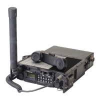
General Dynamics C4 Systems URC-200 (V2)
28
The transmitter may be modulated with either AM or FM modulation using either Plain Text
(audio) or Cipher Text (data) signals. Both the Plain Text and Cipher Text signals are processed
through the same filtering and amplification circuitry used to process the baseband signals in the
receive mode. A VOGAD (Voice-Operated Gain-Adjusting Device) is used for amplification and
automatic gain control of the PT (audio) from the handset microphone or remote high-level
balanced audio input.
For AM modulation, the modulation signal is applied to the VCA and is superimposed on the VCA
control voltage from the ALC. In this way, the modulation signal varies the attenuation of the VCA
which causes the transmit output power amplitude to vary directly in response to the modulation
signal. This produces an AM modulated transmit signal.
For FM modulation, the modulating signal is sampled by an analog to digital converter. A CPLD
re-formats the data stream and then applies the modulation data to the synthesizer PLL chip. The
PLL chip uses the data to dynamically change the programmed frequency of the synthesizer,
producing an FM modulated transmit signal.
In addition to Plain Text or Cipher Text operation, the transmitter can be set to transmit an
emergency beacon signal. The beacon signal is generated by an oscillator in the audio circuitry.
The beacon signal is an audio tone that is swept from 300 Hz to 1 kHz at a 1 second rate. When the
beacon is activated, the transmitter continuously transmits the beacon signal, allowing other
stations to locate the beacon transmitter using standard direction finding techniques.
3.4 30-90 MHz Option Functional Description
The 30-90 option (01-P37240N) operates in the Low VHF frequency band of 30.0000 to 90.0000
MHz in FM mode (only). The 30-90 option can transmit and receive both plain text (PT) and
encrypted voice or data messages (Cipher Text - CT).
The 30-90 MHz option only has 12.5 kHz and 25 kHz tuning increments.
Transmitter output power is 5W, 1W, or 150mW.
Although the 30-90 option has its own separate external RF interface, and is in effect a separate
transceiver from the main radio, it shares a dedicated interface with the main radio’s APPS board
(for processor control, audio circuitry, DC power, and display / keypad functions), and bears many
similarities to the main radio architecture at the top level. The 30-90 has its own synthesizer and
transmit-receive chain. A 2.1 MHz reference from the APPS board determines its shared frequency
stability of 1 part per million (ppm) with the main radio. A simplified block diagram of the 30-90
option is easily derived from Figure 5 for the main radio by simply ignoring references to AM and
showing the physical boundary between the 30-90 and APPS boards / functions. Otherwise, the
simplified block diagram is identical, as depicted in Figure 9.

 Loading...