General Dynamics C4 Systems URC-200 (V2)
33
4.0 OPERATING INSTRUCTIONS
This section provides information for operating the URC-200 (V2) Transceiver. It includes a
functional description of all operating controls, indicators, and connectors and procedures for set-up
and operation.
4.1 Transceiver Placement and Antenna Sighting
The transceiver operates in the VHF and UHF frequency bands, and so uses Line-Of-Sight (LOS)
frequencies. Therefore, placement of the transceiver and antenna sighting greatly affects the
operating range. The longest range is normally obtained when a direct LOS is maintained between
the transceivers. Use of hilltop or tower locations will increase the LOS range. Location in valleys
with intervening hills, behind buildings or in dense woods may reduce or prevent communications.
If possible, avoid locations near electrical interference sources, such as power and telephone lines,
radars, welders and electrical generators.
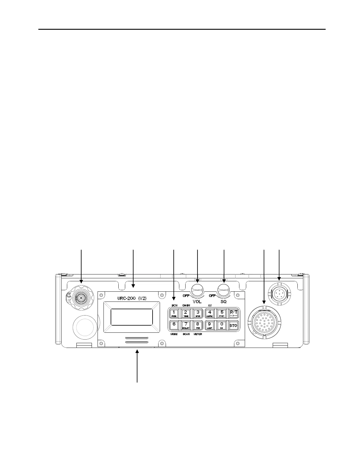
4.2 Controls, Indicators And Connectors
The URC-200 (V2) uses a microprocessor to control and display all operating functions. A keypad
with 12 key switches is used with a Liquid Crystal Display (LCD) to select frequencies and
operating modes for each of the 10 preset channels and to store each channel's operating
parameters. Separate volume and squelch controls are provided to adjust the handset and
loudspeaker audio level and the receiver squelch threshold. The controls, indicators and connectors
shown in Figure 11 are described in Table 7. The display and key-pad functions are shown and
described in Figure 12.