General Dynamics C4 Systems URC-200 (V2)
26
band is inverted.) The LO is used to mix with the RF signal to produce a 45.0 MHz IF signal. A
second LO at 55.7 MHz is mixed with 45.0 MHz IF to produce a 10.7 MHz IF within the receiver.
The processor provides data and clock signals that are used to set the volume controls. An enable
line channels the data to the volume control. A Receive/Transmit (R/T) control signal
activates/deactivates the receiver circuitry and switches the audio circuitry to receive or transmit
operation as desired. The squelch control signal supplied by the processor activates/deactivates the
audio circuitry depending on the squelch threshold. FM/AM and PT/CT control signals switch in
the appropriate demodulation and audio processing paths while separate VHF and UHF control
signals select the appropriate signal path (VHF or UHF) within the preselector. The preselector also
receives tuning voltages from the processor circuitry. The tuning voltage tunes the varactor tuned
preselector filters to the desired receive frequency.
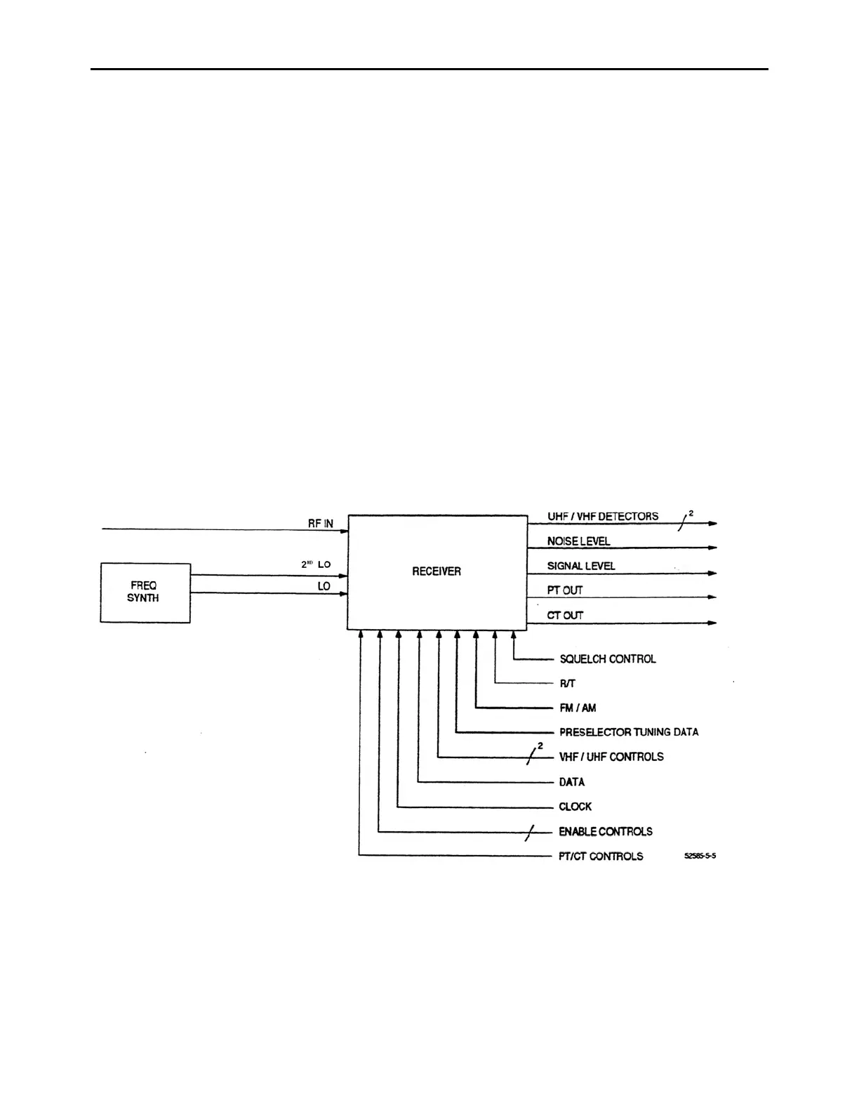
3.2.2 Receiver Output Signals
As shown in Figure 7, the receiver has six output signals. The VHF and UHF Detector signals
provide calibration data to the processor. The Noise Level and Signal Level signals control squelch
operation. The PT and CT output signals are the demodulated baseband signals with the Plain Text
(PT) signal being an audio signal with a 300 Hz to 3 kHz bandwidth while the Cipher Text (CT)
signal is a data signal with a typical data rate of 16 kbps. The bandwidth of the Cipher Text data
signal is from 30 Hz to 10.24 kHz.
Figure 7 - Receiver Output Signal Diagram