General Dynamics C4 Systems URC-200 (V2)
45
4.5.1 Select Scan Channels
Selecting preset channels changes the currently selected preset and updates the current preset
channel number in the EEPROM. Excessive use of this command may result in the transceiver
always starting in preset channel 0 at power up. (Reference: Paragraph 4.4.6.7 and Table 11, “C”
code.)
4.5.2 Cancellation of Presets
Cancelling presets initializes all channels to a default configuration (AM, low power, 225 MHz
receive and transmit, PT, wideband and off scan list). (Reference Paragraph 4.4.2 and Table 11, “I”
code.)
4.5.3 Select Preset Channels
Selecting preset channels changes the currently selected preset and updates the current preset
channel number in the EEPROM. Excessive use of this command may result in the transceiver
always starting in preset channel 0 at power up. (Reference: Paragraph 4.4.6.1 and Table 11, “P”
code.)
4.5.4 Storing Presets
Storing presets allows the user to change the stored information for the current reset channel.
(Receive/transmit frequency, and selection of AM or FM.) Excessive use of the Q command may
result in defective channel data and/or the transceiver may always start in preset channel 0 at power
up. (Reference: Paragraph 4.4.6.6 and Table 11, “Q” code.)
4.5.5 Alignment Command Limitations
The warp command should be used only as needed. This command is used to adjust the crystal
reference oscillator warp value which effects the frequency accuracy in parts per million. This
value should rarely require adjustment (typically once a year or less often). For information
concerning the warp alignment command, please contact General Dynamics Customer Service.
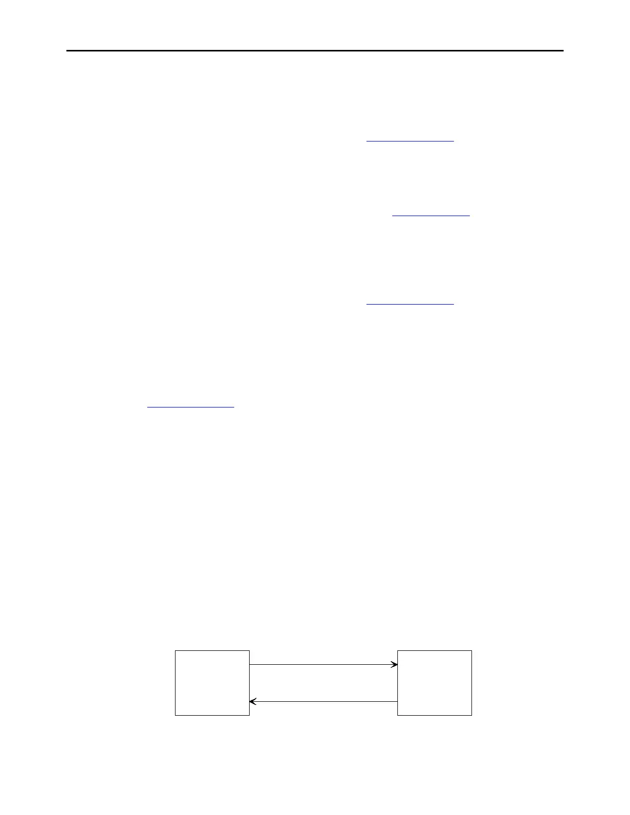
4.6 Remote Operation
The URC-200 (V2) can be operated remotely using one of the available Remote Control Units
(UEC-120 or UEC-220) or by using a personal computer. The Remote Control Unit (RCU) shown
in Figure 13 represents a remote terminal unit (a handset, or a control head connected by a cable of
up to 250 ft). As shown, the RCU is connected in a master/slave relationship to the transceiver and
the RCU always initiates a given command. All commands are sent as a series of ASCII characters
over the RS232 connection.
RCU RADIO
(MASTER) (SLAVE)
Figure 13 - Remote-Control Unit