General Dynamics C4 Systems URC-200 (V2)
35
Table 7 - Front Panel Controls, Indicators and Connector and Rear Panel Connectors
(Continued)
Item
No.
Indicators,
Type Function
9 Battery
connector
J1
(Located on
back-panel)
6-pin battery
connector
Connects transceiver to a power source such as the UBC-100
battery case or UAC-100 AC supply. See Paragraph 1.7 for
power source options.
10 Battery
connector
J5
(Located on
back-panel)
6-pin battery
connector
Connects transceiver to a power source such as the UBC-100
battery case or UAC-100 AC supply. See Paragraph 1.7 for
power source options.
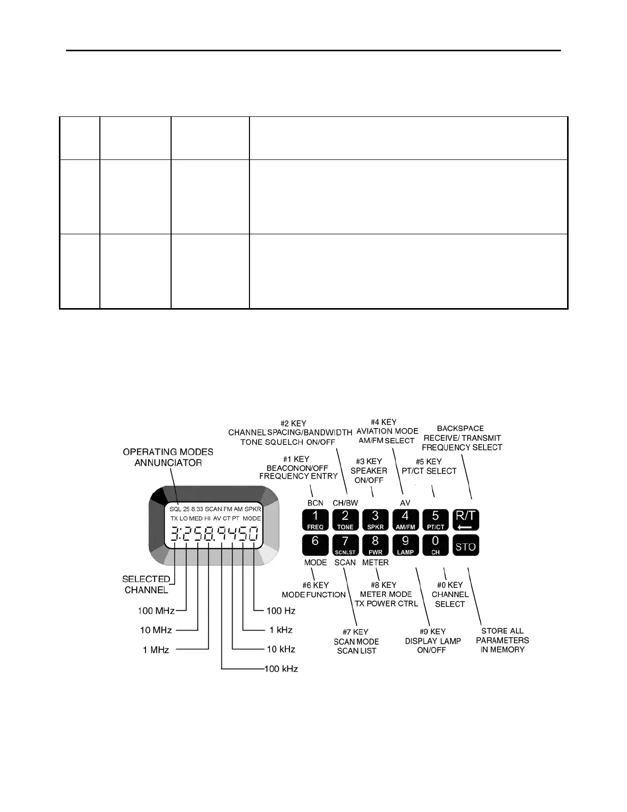
4.3 Keypad and Display Functions
The following procedures describe how to set-up the transceiver for operation in any of the possible
operating modes. Figure 12 shows the display and the key-pad and identifies the key functions.
Each will be discussed in further detail as specific operating modes are described.
Figure 12 - Key-pad and Display Functions