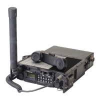
General Dynamics C4 Systems URC-200 (V2)
132
7.1.3 Rack Mounted Base System Operation
7.1.3.1 UAC-350 Operation:
1) Ensure the transceiver and power amplifier ON/OFF switches are set in the OFF
position.
2) Connect the UAC-350 output cable to the DC input of the UIB-100 interface box.
3) Using the supplied IEC type power supply cord, connect the UAC-350 input to a
suitable AC power source.
7.1.3.2 URC-200 (V2) Operation:
1) Set the transceiver ON/OFF switch to the ON position.
2) Program the following settings via the front panel or remote control unit:
Operating frequency
AM or FM modulation mode selection
PT (audio) or CT (data) mode selection
Power level to LOW in AM mode or MED in FM mode for connection to the
power amplifier
Speaker ON or OFF
Scan or Beacon modes (if desired)
3) Set the squelch setting to full counterclockwise, and then turn clockwise until
receiver noise is not heard.
NOTE
Squelch may be set to OFF (fully clockwise) depending on the
operation of the baseband system connected to the transceiver
input.
7.1.3.3 UPA-55H Operation:
1) Set the front panel switches:
AM or FM selection to match the URC-200 (V2)
VHF or UHF selection to match the URC-200 (V2)
Amplifier power output level to LOW or HIGH
Speaker ON or OFF
Scan or Beacon modes (if desired)
2) Set the power amplifier ON/OFF switch to the ON position.
NOTE
The UPA-55H output power level cannot be controlled by the URC-
200(V2). It is controlled by the power amplifier front panel switch.

 Loading...