General Dynamics C4 Systems URC-200 (V2)
119
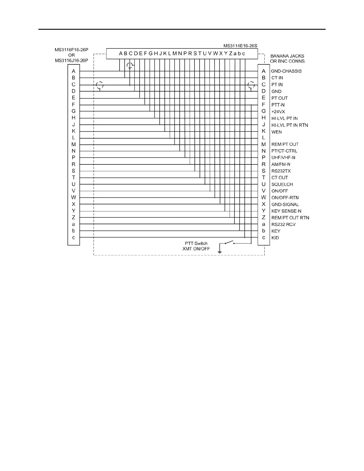
Figure 18 - Breakout Box Schematic
When performing the Receiver Tests in accordance with Paragraph 5.3.2 and Figure 16:
● For the PT OUT on pin E of the Breakout Box, Pin D is the ground return.
● For the CT OUT on pin T of the Breakout Box, Pin D is the ground return.
When performing the Transmitter Tests in accordance with Paragraph 5.3.3 and Figure 17:
● For the CT IN on pin B of the Breakout Box, Pin D is the ground return.
● For the HI-LVL PT IN on pin H of the Breakout Box, Pin J is the ground return.
5.4 Inspection
Inspect for signs of wear, corrosion or other deterioration of exposed surfaces. Ensure mounting
hardware is secure and free of corrosion. Inspect cables and connectors for signs of wear. Ensure
heatsinks and other thermal radiating surfaces are free of dust or other blockage that could impede
airflow and result in overheating of components. Replace or repair as required.
5.5 Troubleshooting
The following eight error messages are produced by the URC-200 (V2) Transceiver and are
displayed on the front panel screen. The displayed error, the error title, and a description of the
error are indicated below in Table 24.