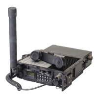
General Dynamics C4 Systems URC-200 (V2)
29
Figure 9 - 30-90 MHz Transceiver Simplified Functional Block Diagram
In receive mode, the RF signal arrives at the 30-90 antenna port and is passed through a
coupler/detector which is used only in transmit mode. A solid state Transmit/Receive switch is used
to connect the RF signal path to the receiver circuitry. In the receiver, the RF signal is first passed
through a preselector that uses a self-tuned bandpass filter to reject all out-of-band signals and to
provide some signal amplification. Received signal is then mixed with a Local Oscillator (LO)
signal provided by the synthesizer to produce a 10.7 MHz Intermediate Frequency (IF) signal. This
first IF signal is then filtered and applied to an integrated 2nd IF/Baseband chip, which produces
demodulated FM signal using a 10.245 MHz IF frequency. The APPS board audio circuitry
provides appropriate filtering and amplification of the baseband signal that is then applied to the
speaker and/or front panel audio and remote connectors, as determined by operating mode. It
should be noted that the 30-90 does not employ a delayed AGC scheme in the receive RF chain, as
does the main radio receiver.
In transmit mode, the synthesizer is programmed to generate an RF signal at the desired transmit
frequency. This RF signal is amplified and applied to a Voltage Controlled Attenuator (VCA) that
is used to regulate signal strength applied to the RF amplifier. The RF signal is amplified to desired
output power by the RF amplifier and then filtered by a bandpass filter to reduce harmonic and
spurious transmit signals. The RF signal then passes through a coupler/detector that senses signal
strength of the transmitted RF signal. The coupler/detector provides a control voltage to the
Automatic Level Control (ALC) circuitry that then sets the appropriate attenuation level of the
VCA. The coupler/detector also senses reverse power to detect a high VSWR condition. When a
high VSWR is detected, the coupler/detector provides a control voltage to the ALC that reduces
output power so the RF amplifier is not damaged. For FM mode, the modulation signal is applied
directly to the synthesizer and produces an FM modulated RF signal.

 Loading...