General Dynamics C4 Systems URC-200 (V2)
31
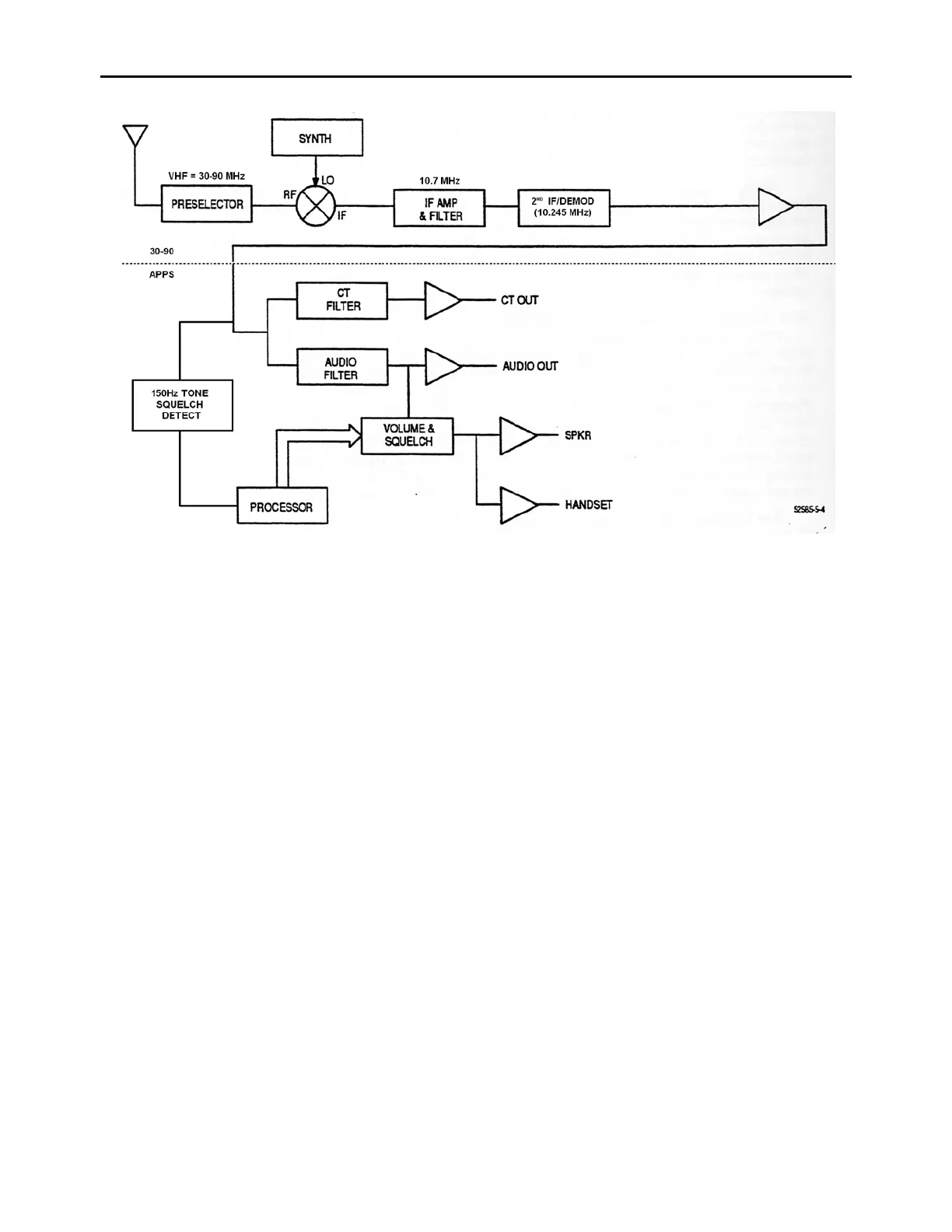
Figure 10 - 30-90 Receiver Functional Block Diagram
3.4.2 30-90 MHz Transmitter Functional Description
Refer to Figure 8 for the functional block diagram for the transmitter. In the transmit mode, the
synthesizer generates the transmit signal at the operating frequency in response to frequency data
supplied by the processor. The transmit signal is amplified and applied to the Voltage Controlled
Attenuator (VCA). The VCA is used to adjust the RF drive level to the RF Amplifier by varying
the amount of attenuation of the transmit signal. The VCA is controlled by the ALC that uses inputs
(VFWD) from the output power detectors to determine the amount of attenuation needed. The ALC
also uses inputs (VREFL) from the coupler/detector to determine the reflected power (VSWR)
level of at the antenna port. A high VSWR can cause damage to the transmitter, so if a high VSWR
is detected, the ALC cuts back the output power accordingly to prevent over stressing the final RF
amplifier. Together, the VCA, ALC, and output coupler/detectors form a closed loop that regulates
the transmitter output power and protects the transmitter from damage in case of an antenna or
internal circuitry malfunction.
After passing through the VCA, the transmit signal is applied to the final RF amplifier. The final
RF amplifier is a fixed gain amplifier which amplifies the transmit signal to a maximum of 5 Watts
average power at 80% modulation (3.79 Watts CW power). The actual output power level is
determined by the drive level from the VCA, which is controlled by the ALC. The ALC uses a
closed analog loop to set the output power to the desired output level as determined by the
processor. After final amplification, the transmit signal is passed through a bandpass filter to reduce
harmonic and spurious transmit signals, through a solid state T/R switch which switches the
antenna between the transmitter and receiver as needed, and through a coupler/detector which