to one of two proper positions (HIGH, LOW) – two metal pins must fit with two
holes in the probe. Tighten the white plastic screw back into the holder, connect the
black plastic connector.
Now the probe is ready for use. The connection between the probe and the
control unit is provided via Bluetooth communication. See the chapter Using
Bluetooth adapter for remote control.
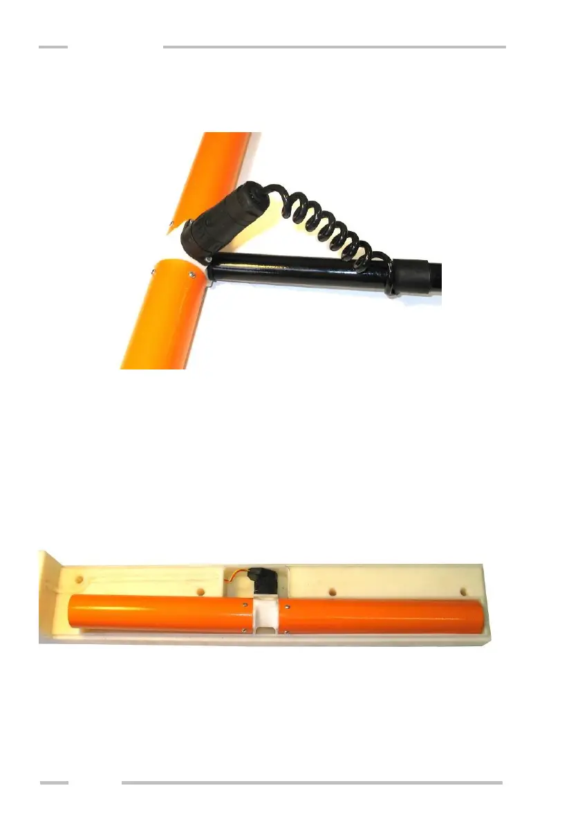
Sledge for continuous measurement
Dismantle the top cover of the sledge (fixed by five plastic screws), insert
the probe and connect the connector. Put the cover back and tighten all five plastic
screws by wrench from accessories.
If you wish to measure with maximum depth range (HIGH), turn the sledge
so that label “Hi” is on its upper side. If you wish to measure with half depth range
(LOW), turn the sledge so that the label “Lo” is on its upper side.