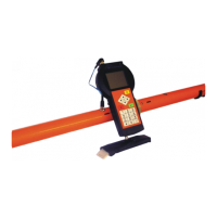
An example of the file:
Latitude Longitude Altitude Cond. [ms/m] Inphase [ppt] Error[%] Note
4914.51012N 01634.80651E 269.73 34.15 2.27 0.1
4914.51066N 01634.80658E 269.56 34.12 2.31 0.1 stone
4914.51091N 01634.80664E 268.56 34.14 2.33 0.2
- .interpolated.dat is ASCII file like ”.dat”. This file is generated only from
continuous measurements (both manual and GPS). The positions of
measured points without primary position information (data measured
between length marks or between valid GPS data positions) are
interpolated between data with known positions.
- .xyz is ASCII file, which is possible to import directly to IX1D inversion
software (the software for EM inversion). The file is generated only from
CMD-Explorer / MiniExplorer measurements. Conductivities are not
converted to resistivities. If factory calibration was used for measurement,
conductivities are recalculated according to IX1D convention to obtain
correct conductivities after inversion. Positions are saved without
interpolation. If GPS positions are not converted to UTM coordinates,
positions are always converted to decimal format in degrees “dd.ddddd”
and multiplied by 100 000. Using the IX1D software for data import use
File / Import / XYZ data file / EM conductivity data. Select HMD ONLY
for data measured in half depth range (Low) or VMD ONLY for data
measured in full depth range (High). Select HMD first. Select appropriate
column numbers.
- .interpolated.xyz is ASCII file like “.xyz”. This file is generated only from
continuous measurements (both manual and GPS). The positions of
measured points without primary position information (data measured
between length marks or between valid GPS data positions) are
interpolated between data with known positions.
- .srf_map.dat – is ASCII file for 3D mapping using XYZ contouring
software. This file is generated only from CMD-Explorer / MiniExplorer
measurements. The measured conductivity (apparent conductivity as well
as the true conductivity – the result of built-in in-situ 1D inversion) is
distributed between depth layers. Setting of the maximum depth and
number of layers is possible in the menu Export settings / Surfer data
format. For creating any depth slice import three certain columns from the
file to the contouring software (e.g. Surfer). First two columns contain XY
(or Lat-Lon) coordinates, other columns contain Z data. E.g. column
labeled “AppCond/0.50-1.00” contains apparent conductivity between
depth 0.5 m and 1.0 m, column labeled “Cond/1.50-2.00” contains true