14
Instruction manual
Electric Actuators Type EA15-250
3.6 Principle of operation
The actuator runs by switching the voltage from the OPEN position to the CLOSE position. By switching the voltage to the other
input, the actuator runs from the CLOSE position to the OPEN position.
The end positions are factory set to 0 and 90°. Additionally for types EA25-250, any 3rd position (MIDDLE position) can be adjusted,
which is located between the OPEN position and the CLOSE position. This position is not assigned at the factory.
End positions and Middle position can later be changed via the end position buttons, see Chapter “Adjusting end positions”.
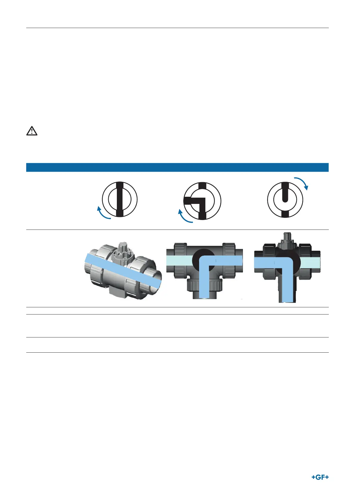
3.6.1 Position indicator
The position indicator shows the valve position. The valve positions can be read on the installed cover.
NOTE!
GF actuators are always delivered in the OPEN position.
When the cover is installed, the following image can be seen (Example ball valve):
2-way 3-way horizontal (L)* 3-way vertical (L)*
Image of position
indicator in valve-
position 1
DC
A
B
DC
A
B
DC
A
B
Valve function
A
B
C
D
B
C
A
Actuating angle 0° - 90° 0° - 90° 0° - 180°
Valve-position 1 A-B
(OPEN)
A–C
(Flow right side, outlet to the
front)
B-C
(Flow left side, bottom outlet)
Valve-position 2 C-D
(CLOSE)
B–C
(Flow left side, outlet to the front)
A-C
(Flow right side, bottom outlet)
*EA25-250