18
Instruction manual
Electric Actuators Type EA15-250
3.7 Wiring
Standard actuators: Provided with DIN-Plugs from factory. Follow diagrams below.
cULus marked actuators: Provided with cable glands. Connect open wired directly to Terminals 1-N.
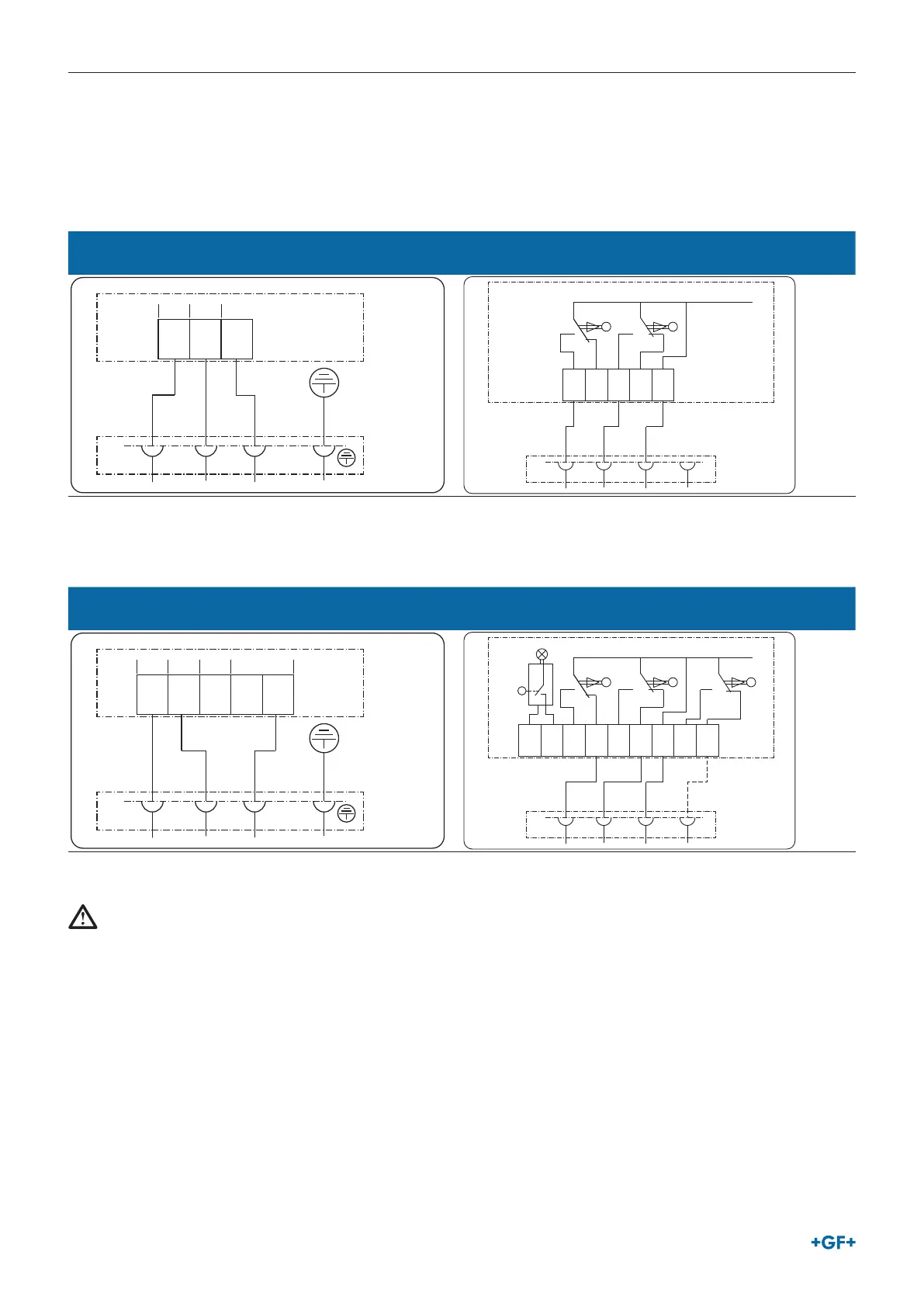
3.7.1 EA15 wiring diagram
Connection of the voltage supply
for positions OPEN and CLOSE
Connection of position feedback
for positions OPEN and CLOSE
1 2 N
connection
terminals
green/yellow
connector
blackredgreen
1 2 3
open close
PE – Protective
Earth IEC60364
7 8 9 1011
Connection
terminals
closeopen
Connector
blackwhitered
max. 2A @
30V DC
NO NC NO NC COM
1 2 3 4
3.7.2 EA25-250 wiring diagram
Connection of the voltage supply
for positions OPEN, CLOSE and MIDDLE
Connection of position feedback
for positions OPEN, CLOSE (MIDDLE optional)
1 2 3 4 N
connection
terminals
green/yellow
connector
blackredgreen
1 2 3
open close
middle
permanent
PE – Protective
Earth IEC60364
5 6 7 8 9 10111213
Connection
terminals
Ready to
operate
close middleopen
green
Connector
blackwhitered
COM
Relay ratings:
Relays: Max. 6A @
either 230VAC or
24VDC
Caution: Do not mix
24VDC and 230VAC!
Apply only one
voltage-level!
NO NO NC NO NC COM NO NC
1 2 3 4
WARNING!
No mixed voltage sources!
Do not connect mixed voltage potentials or voltage sources on the feedback relays. Only use one single power voltage source to
connect to terminals 1, 2, 3 or 4. Do not supply power voltage from dierent voltage sources to one actuator!
► Either connects 230VAC or 24VDC the feedback relays.
► Do not connect 230VAC and 24VDC at the same time.
► Also ensure the voltage is supplied from one single source to all relay contacts at all times.