16
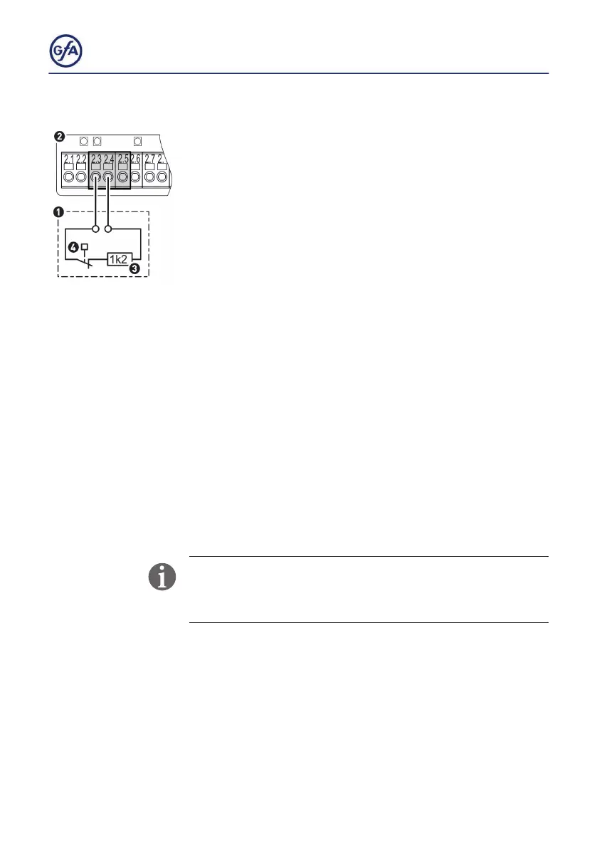
Pneumatic safety edge
Connect the pneumatic safety edge with a terminal resistance
of 1k2 (3) as follows:
▪ Install the product according to the manufacturer‘s instructions.
▪ Connect the cables of the product to terminals X2.3 and X2.4
of the door control (2) as shown (1).
▪ You can connect a second safety edge to terminals X2.6 and
X2.7 in the same way.
▪ Makesurethattherubberproleiscompressedinthenal
limit position CLOSE.
▪ Activate the safety edge after completion of the electrical
installation with menu item
0.1.
Automatic test of the pneumatic safety edge:
▪ With each activation of the pre-limit switch is, the door
control tests automatically whether the pneumatic switch (4)
triggers.
▪ If the door control does not receive a signal from the
pneumatic switch within 2 seconds, fault indication
F 2.8.
appears.
If the safety edge is activated or if the circuit is permanently
interrupted, fault indication
F 2.6. appears.
Fault indication
F 2.7. appears in case of a short circuit.