115
Detail program description - Control adjust | Helicopters
Thr6
0%
+88%I5
Thr6
Gyr7
I8
TYP
+111%
0.0 0.0
– travel + –time+
0%
+100%
+100%
0.0 0.0
0%
+100%
+100%
0.0 0.0
0%
+100%
+100%
0.0 0.0
GL
GL
GL
fr
fr
fr
---
---
---
Offset
GL
Normal
7
8
In principle, the helicopter program also permits
the individual inputs to be assigned to any existing
transmitter control (proportional controls and
switches).
However, please note here that some of the inputs
available on this menu are already assigned to
helicopter-specifi c functions, and therefore cannot be
re-assigned in this way.
Nevertheless, the receiver layout on page 65 indicates
that the throttle servo or the speed controller of an
electrically-powered helicopter must be connected
to receiver output "6", since control channel "6" is
reserved for motor power regulation.
Unlike a fi xed-wing model aircraft, the throttle servo
or speed controller is not directly controlled by the
joystick or other transmitter control but rather by a
complex mixer system, see »Helicopter mixer« menu
beginning page 176. Furthermore, the "Throttle limit
function" described on the next page also infl uences
this mixer system.
Assigning a transmitter control or switch on the
"Throttle" line, or to its supplementary control signal,
would unnecessarily "confuse" this complex mixer
system. For this reason the "Throttle" input MUST
be left "free".
0%
+88%I5
Thr6
Gyr7
I8
TYP
+100%
0.0 0.0
– travel + –time+
0%
+100%
+100%
0.0 0.0
0%
+100%
+100%
0.0 0.0
0%
+100%
+100%
0.0 0.0
GL
GL
GL
fr
fr
fr
---
---
---
Offset
GL
Normal
7
8
Another brief tap on the center SET key of the right
touch pad will complete the entry.
Negative and positive parameter values are possible
in order to appropriately adapt the control's direction
or effect.
A simultaneous tap on the cd or ef keys of the
right touch pad (CLEAR) will reset the changed
parameter displayed in inverse video back to
"+100 %".
Important:
In contrast to altering servo travel, changing the
control travel setting affects all "downstream" mixer
and coupling inputs, i.e. any and all servos that could
be actuated by the transmitter controls concerned.
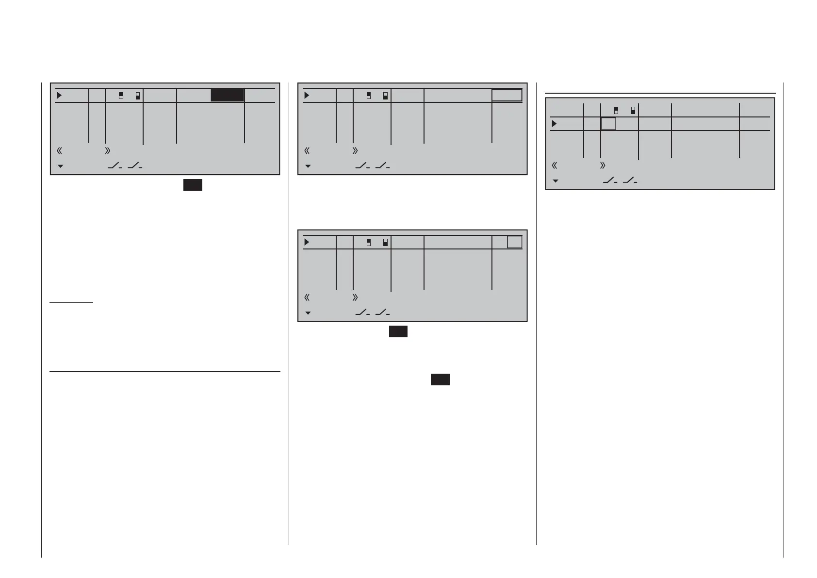
Column 6, "– time +"
Each of the function inputs, I5 … 16, can be assigned
a symmetric or asymmetric time delay of between 0
and 9.9 s.
Move the marker frame to the right beyond the
column labeled "– travel +" with the f selection key
of the left or right touch pad.
To set a symmetric time delay, i.e. control-side
independent, move the affected transmitter control
(proportional control or switch) as necessary to a
position such that the marker frame encloses both
sides of the time setting.
0%
+111%I5
Thr6
Gyr7
I8
TYP
+111%
0.0 0.0
– travel + –time+
0%
+100%
+100%
0.0 0.0
0%
+100%
+100%
0.0 0.0
0%
+100%
+100%
0.0 0.0
GL
GL
GL
fr
fr
fr
---
---
---
Offset
GL
Normal
7
8
To set an asymmetric time delay, move the affected
operating element (transmitter control or switch) as
necessary to a position such that the marker frame
encloses only the value to be changed.
0%
+111%I5
Thr6
Gyr7
I8
TYP
+111%
0.0 0.0
– travel + –time+
0%
+100%
+100%
0.0 0.0
0%
+100%
+100%
0.0 0.0
0%
+100%
+100%
0.0 0.0
GL
GL
GL
fr
fr
fr
---
---
---
Offset
GL
Normal
7
8
Briefl y tap the center SET key of the right touch pad
to activate value setting. The value fi eld is shown
highlighted. Values can be changed with the selection
keys of the right touch pad.
Another brief tap on the center
SET key of the right
touch pad will complete the entry.
A simultaneous tap on the cd or ef keys of the
right touch pad (CLEAR) will reset the changed
parameter displayed in inverse video back to 0.0.

 Loading...


