114 Detail program description - Control adjust | Helicopters
The display will then present the switch number
together with a symbol indicating the given switch
direction. At the same time, the column label in the
footer line will change from SEL into another switch
symbol.
0%
+100%I5
Thr6
Gyr7
I8
TYP
+100%
0.0 0.0
– travel + –time+
0%
+100%
+100%
0.0 0.0
0%
+100%
+100%
0.0 0.0
0%
+100%
+100%
0.0 0.0
GL
GL
GL
fr
fr
fr
---
---
---
Offset
GL ---
Normal
7
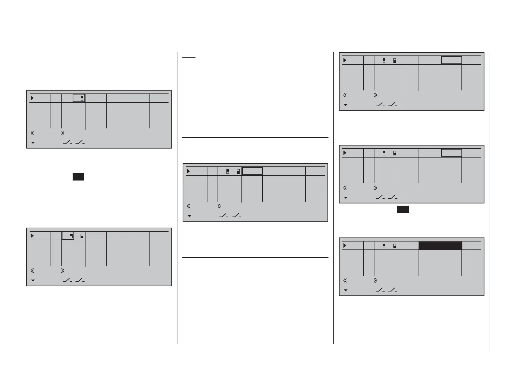
Now put the 3-way switch back into its middle position.
Move the marker frame as necessary to the left into
the column labeled with the new switch symbol, briefl y
tap on the center
SET key of the right touch pad then
assign the switch's other switch direction by once
again starting from the middle position but this time
move the switch in the other direction.
The display will now present the given switch number
together with a symbol indicating the given switch
direction.
0%
+100%I5
Thr6
Gyr7
I8
TYP
+100%
0.0 0.0
– travel + –time+
0%
+100%
+100%
0.0 0.0
0%
+100%
+100%
0.0 0.0
0%
+100%
+100%
0.0 0.0
GL
GL
GL
fr
fr
fr
---
---
---
Offset
GL
Normal
7
8
A simultaneous tap on the cd or ef keys of the
right touch pad (CLEAR) while on an input line with
an active transmitter switch assignment – see above
fi gure – will reset the input back to "fr" and "---".
Tips:
When assigning switches, pay attention to the •
desired switching direction and also that all
unused inputs remain "free" or are again reset to
"free". This is necessary to ensure that inadvertent
actuations of these unused controls cannot cause
malfunctions.
The travel setting described below allows the •
appropriate end state to be established for an
assigned switch.
Column 4, "offset"
The control center for the given control, i.e. its zero
point, can be changed in this column. The adjustment
range lies between -125 % and +125 %.
0%
+100%I5
Thr6
Gyr7
I8
TYP
+100%
0.0 0.0
– travel + –time+
0%
+100%
+100%
0.0 0.0
0%
+100%
+100%
0.0 0.0
0%
+100%
+100%
0.0 0.0
GL
GL
GL
fr
fr
fr
---
---
---
Offset
GL
Normal
7
8
A simultaneous tap on the cd or ef keys of the
right touch pad (CLEAR) will reset the entry fi eld
value displayed in inverse video back to "0 %".
Column 5, "–travel+"
This column is used to set servo travel symmetrically
or asymmetrically for each side. The setting range is
±125 % of normal servo travel.
Use the cd selection keys of the left or right touch
pad to select an input: I5, Thr6, Gyr7, I8 … 15 or
Tl16.
To set symmetric travel, i.e. control-side independent,
put the respective operating element (proportional
control or switch) into a position where the marker
frame encloses both sides of the travel setting.
0%
+88%I5
Thr6
Gyr7
I8
TYP
+111%
0.0 0.0
– travel + –time+
0%
+100%
+100%
0.0 0.0
0%
+100%
+100%
0.0 0.0
0%
+100%
+100%
0.0 0.0
GL
GL
GL
fr
fr
fr
---
---
---
Offset
GL
Normal
7
8
To set asymmetric travel, the respective control
(proportional control or switch) is to be moved to
the side to be set such that the marker frame only
encloses the value to be changed.
0%
+100%I5
Thr6
Gyr7
I8
TYP
+111%
0.0 0.0
– travel + –time+
0%
+100%
+100%
0.0 0.0
0%
+100%
+100%
0.0 0.0
0%
+100%
+100%
0.0 0.0
GL
GL
GL
fr
fr
fr
---
---
---
Offset
GL
Normal
7
8
Briefl y tap the center SET key of the right touch pad
to activate value setting. The value fi eld is shown
highlighted. Values can be changed with the selection
keys of the right touch pad.
0%
+111%I5
Thr6
Gyr7
I8
TYP
+111%
0.0 0.0
– travel + –time+
0%
+100%
+100%
0.0 0.0
0%
+100%
+100%
0.0 0.0
0%
+100%
+100%
0.0 0.0
GL
GL
GL
fr
fr
fr
---
---
---
Offset
GL
Normal
7
8

 Loading...


