182 Detail program description - Helicopter mixer
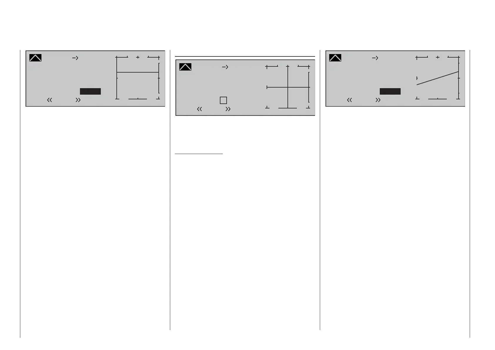
Channel 1
Curve
off Point
Output
Input 0%
+66%
L
+
–
100
¼ O U T P U T
+66%
Throttle
Normal
The value to be set depends both on the speed
controller used and on the target motor speed that is
desired, and can, of course, be varied according to
the fl ight phase.
For auto-rotation fl ight, an automatic switch-over
is made from this mixer to a confi gurable default
value; see page 190.
Channel 1
Curve
off Point
Output
Input +100%
+30%
H
+
–
100
¼ O U T P U T
+30%
Tail rot.
Normal
Starting with values of -30 % for point "L" and +30 %
for point "H", the mixer is to be confi gured in such
a way that the helicopter, even during prolonged
vertically ascending or descending fl ights, does not
deviate from the yaw axis as a result of the main
rotor's altered torque while hovering. For hovered
fl ight, trim should only be affected by way of the
(digital) tail rotor trim wheel.
For a reliable torque compensation setting, it is
essential that the collective pitch and throttle curves
have been set up correctly, i.e. that the rotor speed
remains constant over the collective pitch's full
adjustment range.
This third curve mixer applies only to the control
curve of the tail rotor servo when the throttle/
collective pitch stick is moved, whereas the "Channel
1 curve" (see page 131) acts on all servos that are
affected by the throttle/collective pitch stick. Note that
the output signal of the "Channel 1 curve" option also
functions as an input signal for the tail rotor curve
programmed here: In the graph, the vertical line is
synchronized with the throttle/collective pitch stick
and follows the current Channel 1 curve characteristic
from the »Channel 1 curve« menu.
In the auto-rotation fl ight phase this mixer is
automatically switched off.
Channel 1 ¼ Tail rot. (static torque compensation)
Channel 1
Curve
off Point
Output
Input 0%
0%
+
–
100
¼ O U T P U T
0%
Tail rot.
?
Normal
The default approach here is to preset a torque
compensation curve with a linear mixer ratio of a
uniform 0 %, as is required for a gyro sensor working in
"heading lock mode" – see the screen image above.
Important notice:
In this context, ensure that you comply with
the instructions on adjusting your gyro: if not,
you risk making adjustments that render your
helicopter impossible to fl y.
If, on the other hand, you use your gyro sensor in
the "normal" operating mode, or if it only has what is
termed "normal mode", then confi gure the mixer as
follows:
As with the confi guration of the collective pitch curve
(see page 176), the control curve of the tail rotor
can also be defi ned by up to 6 points. If required,
therefore, you can modify the mixer at any time
and preset both symmetrical and asymmetric mixer
ratios both above and below the hover point. Before
you do, however, ensure you have entered the
correct direction of rotation for the main rotor on the
»Helicopter type« menu.

 Loading...


