234 Detail program description - Telemetry
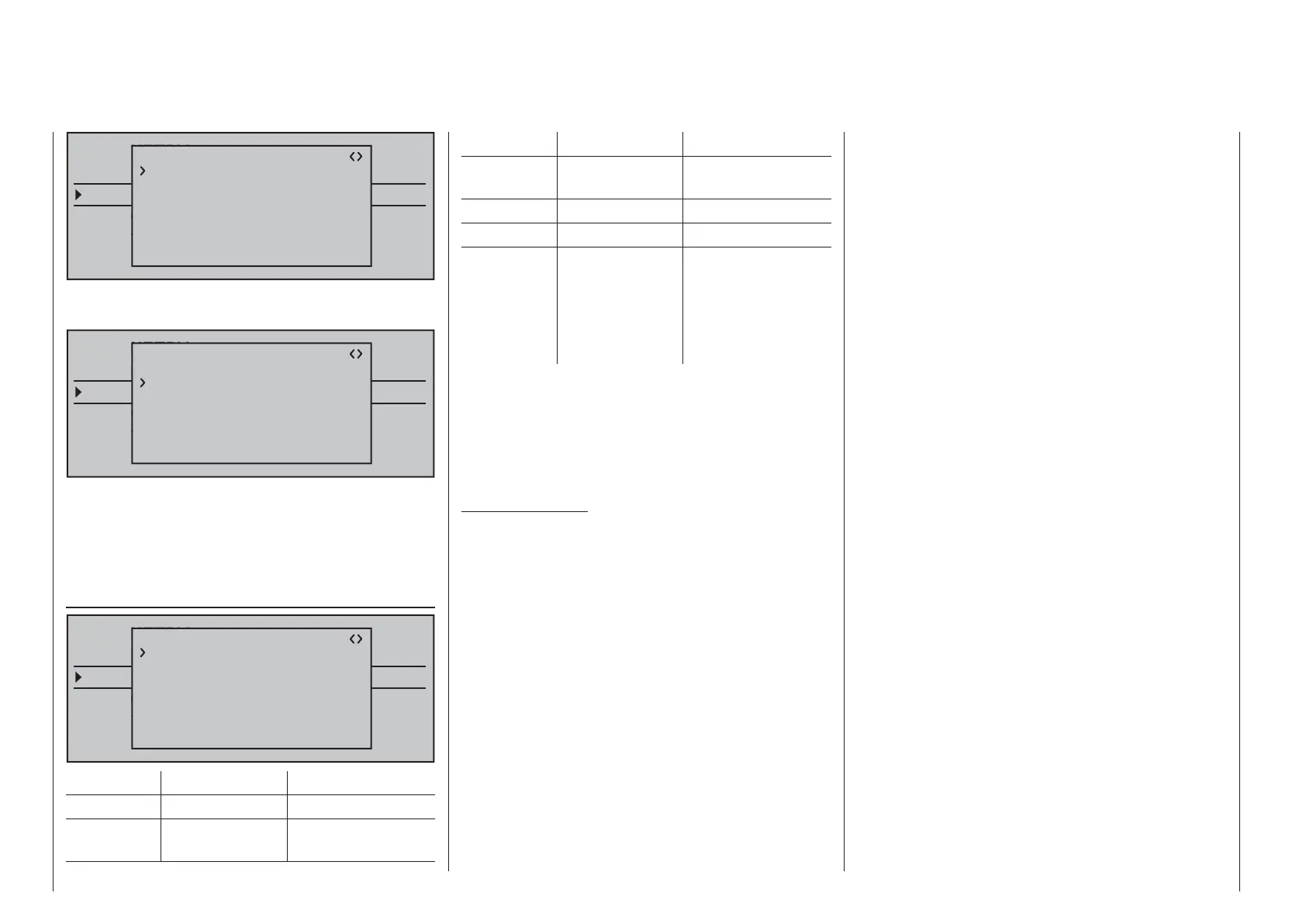
TELEMETRY
SETTING & DATAVIEW
SENSOR SELECT
RF STATUS VIEW
VOICE TRIGGER
TELEMETRI RCV
BIND. 1
RX FAIL SAFE
INPUT CH: 04
MODE : FAI-SAFE
F.S.POS. : 1500sec
DELAY : 0.75sec
OUTPUT CH: 04
POSITION : 1670sec
FAIL SAFE ALL: NO
This is also the case, for example, if this is mapped
with INPUT CH 01:
TELEMETRY
SETTING & DATAVIEW
SENSOR SELECT
RF STATUS VIEW
VOICE TRIGGER
TELEMETRI RCV
BIND. 1
RX FAIL SAFE
INPUT CH: 01
MODE : FAI-SAFE
F.S.POS. : 1420sec
DELAY : 0.75sec
OUTPUT CH: 04
POSITION : 1670sec
FAIL SAFE ALL: NO
In this case, the servo connection 04 would, in turn,
react according to the fail-safe settings of CH 01.
The reaction or delay time set in the "DELAY" line,
on the other hand, always applies uniformly for all
channels set to "FAI(L) SAFE".
RX FREE MIXER
TELEMETRY
SETTING & DATAVIEW
SENSOR SELECT
RF STATUS VIEW
VOICE TRIGGER
TELEMETRI RCV
BIND. 1
RX FREE MIXER
MASTER CH: 00
SLAVE CH : 00
S–TRAVEL–: 100
S–TRAVEL+: 100
MIXER : 1
RX WING MIXER
TAIL TYPE: NORMAL
Value Explanation Possible settings
MIXER Mixer selection 1 … 5
MASTER
CH
Signal source or
source channel
0, 1 … depending
on receiver
Value Explanation Possible settings
SLAVE CH Target channel 0, 1 … depending
on receiver
S-TRAVEL– Admix negative 0 … 100 %
S-TRAVEL+ Admix positive 0 … 100 %
RX WING
MIXER
TAIL TYPE
tail type NORMAL,
V-TAIL (V-LW)
ELEVON
(vertical/horizontal
mixer for delta and
fl ying wing)
MIXER
Up to three mixers can be programmed
simultaneously. Use "MIXER" to switch between
mixers 1 … 5.
The following settings in this display always for just
the mixer selected in the "MIXER" line.
Important notice:
If you have already programmed mixer functions
in the »Wing mixer« or »Free mixer«" Free mixer
" menus, make absolutely sure that these mixers
do not overlap with those in the menu "RX FREE
MIXER"!
MASTER CH ("from")
According to the same principles described in the
section "Free mixer" on page 192, the signal applied
at the MASTER CH (signal source or source channel)
is mixed to a variable extent to the SLAVE CH (target
channel).
Select "00" if no mixer should be set.
SLAVE CH ("to")
The signal of the MASTER CH (source channel)
is mixed proportionally to the SLAVE CH (target
channel). The mix ratio will be determined by the
percentages entered in the lines "TRAVEL–" and
"TRAVEL +".
Select "00" if no mixer should be set.
TRAVEL–/+ (proportion of the admix in %)
With the settings of these two lines the percentage
of the admix is specifi ed in relation to the MASTER
signal separately for each direction.
RX WING MIXER TAIL TYPE (tail unit type)
The following model types are also available in the
"Tail" line of the »Model type« menu, on page 94 and
should, preferentially, be preset there. In this case,
always leave the TAIL TYPE set to NORMAL.
However, if you would prefer to use the mixer
integrated in the receiver, you can select the already
pre-adjusted mixer functions for the corresponding
model type:
NORMAL•
This setting corresponds to the classic aircraft
type with rear tail unit and separate rudder and
elevator. No mixer function is necessary for this
model type.
V-TAIL (V-tail unit)•
With this model type the elevator and rudder
control functions are connected, so that each
of the two tail unit fl aps – each controlled with a
separate servo – assume both the elevator and
rudder function.
The servos are normally connected to the receiver
as follows:
OUTPUT CH 3: Left V-tail servo
OUTPUT CH 4: Right V-tail servo
If the servo's direction of rotation is incorrect,
please observe the notices on page 62.
ELEVON (delta/fl ying wing models)•
The servos connect at the outputs 2 and 3 assume
the aileron and elevator function. The servos are
normally connected to the receiver as follows:
OUTPUT CH 2: Left horizontal/vertical

 Loading...


