235
Detail program description - Telemetry
OUTPUT CH 3: Right horizontal/vertical
If the servo's direction of rotation is incorrect,
please observe the notices on page 62.
RX CURVE (EXPO)
TELEMETRY
SETTING & DATAVIEW
SENSOR SELECT
RF STATUS VIEW
VOICE TRIGGER
TELEMETRI RCV
BIND. 1
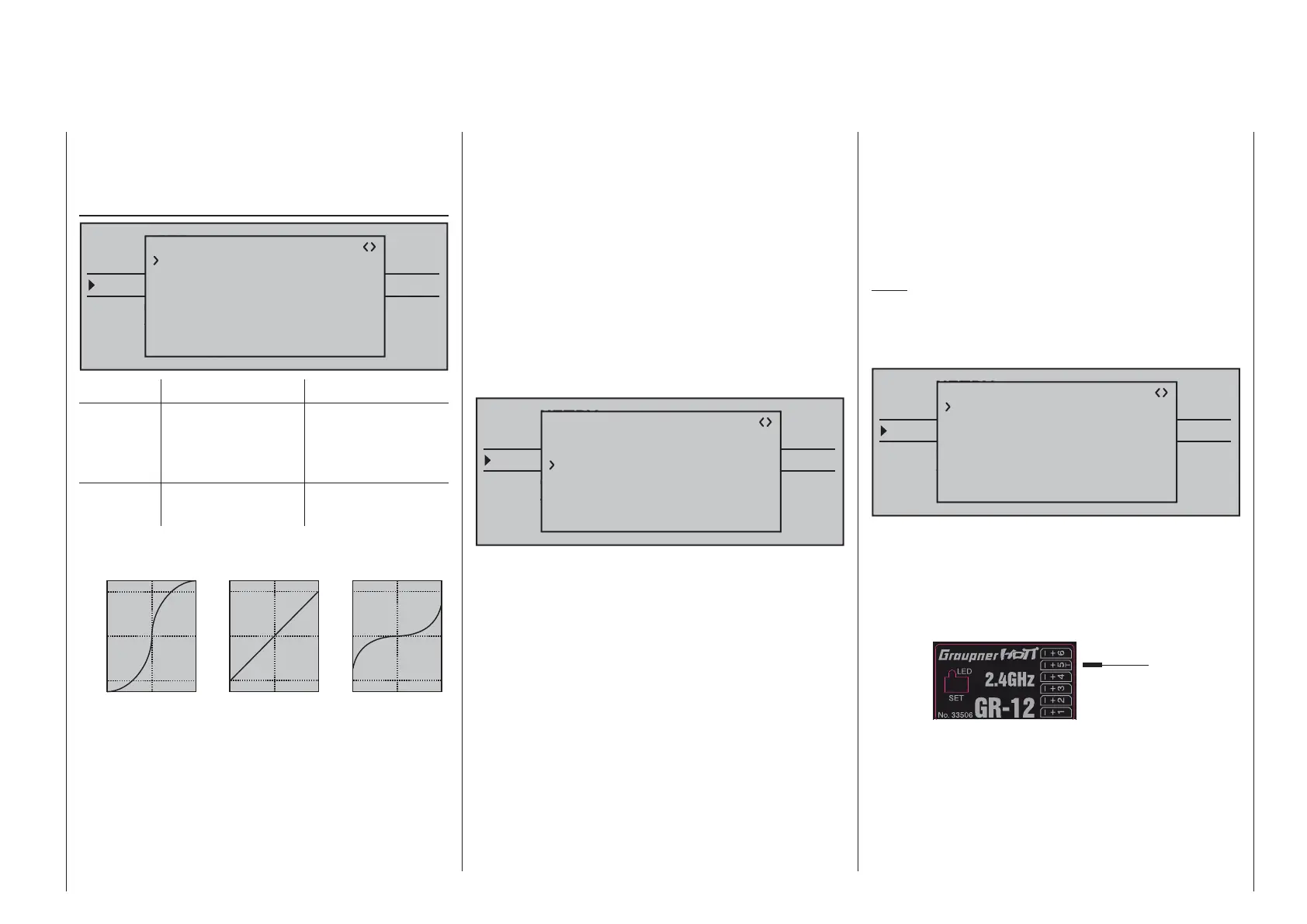
RX CURVE
TYPE : B
CURVE1 CH : 02
TYPE : B
CURVE2 CH : 03
TYPE : B
CURVE3 CH : 04
Value Explanation Possible settings
CURVE1,
2 or 3 CH
Channel
assignment of the
respective curve
setting
1 … depending on
receiver
TYPE Curve type A, B, C
see fi gure
Expo = +100%
–100%
+100%
0
–100%
+100%
0
Expo = –100%
TYPE A
–100%
+100%
0
–100%
+100%
0
linear
–100%
+100%
0
–100%
+100%
0
TYPE B
TYPE C
DR = 125% DR = 70%
Servo travel
Control travel
Servo travel
Control travel
Servo travel
Control travel
Normally a non-linear control function, if applicable, is
used for the aileron (channel 2), elevator (channel 3)
and rudder (channel 4). These channel defaults also
correspond to the factory settings. BUT CAUTION:
This assignment only applies when, on the transmitter
side, neither "2HRSv3+8" is specifi ed in the "Tail
type" line nor is "2AIL" or 2AIL 2FL" specifi ed in the
"Aileron/camber fl aps" line of the »Base settings«
menu. Otherwise, assignments will have already
been made in the transmitter for control function 3
(elevator), which will then be split between control
channels 3 & 8, or control function 2 (aileron), which
will then be split between control channels 2 & 5 for
the left and right ailerons. The corresponding control
channels (INPUT CH) in the receiver would in both
cases be channels 03 & 08 or 02 & 05.
Therefore if, for example, "2AIL" has been specifi ed
on the transmitter side and the intent here is to utilize
the RX CURVE option instead of the
mc-20 HoTT
transmitter's individually adjustable »Dual Rate /
Expo« menu (see page 120 or 124), then two curves
must be set:
TELEMETRY
SETTING & DATAVIEW
SENSOR SELECT
RF STATUS VIEW
VOICE TRIGGER
TELEMETRI RCV
BIND. 1
RX CURVE
TYPE : B
CURVE1 CH : 02
TYPE : B
CURVE2 CH : 05
TYPE : B
CURVE3 CH : 04
Otherwise, the left and right ailerons have different
control characteristics.
With the RX CURVE function you can manage the
control characteristics for up to three servos:
CURVE 1, 2 or 3 CH•
Select the desired control channel (INPUT CH) of
the fi rst servo.
The following setting in TYPE only pertains to the
channel selected here.
TYPE
Select the servo curve:
A: EXPO = -100 % and DUAL RATE = 125 %
The servo reacts strongly to movements of the
joystick around the neutral position. As the rudder
throw increases, the curve becomes fl atter.
B: Linear setting.
The servo follows the joystick movement linearly.
C: EXPO = +100 % and DUAL RATE = 70 %
The servo reacts weakly to the joystick
movements around the neutral position. As the
rudder throw increases, the curve becomes
steeper.
Note:
The control characteristics programmed here also
affect the mapped receiver outputs.
5CH FUNCTION: "SERVO" or "SENSOR"
TELEMETRY
SETTING & DATAVIEW
SENSOR SELECT
RF STATUS VIEW
VOICE TRIGGER
TELEMETRI RCV
BIND. 1
RX CURVE
TYPE : A
CURVE1 CH : 02
TYPE : A
CURVE2 CH : 03
TYPE : B
CURVE3 CH : 04
5CH FUNCTION:SERVO
Some receivers have a specifi c servo connection
which has been made switchable rather than an
independent telemetry connection. Thus, for example,
on the GR-12 receiver included with the mx-12 HoTT
set, order no. 33112, , servo connector 5 has an extra
"T" mark and can be alternatively connected …
Servo
Sensor
OR
… not only via an order no. 7168.6Aadaper cable
to upgrade the receiver but also connected to a
telemetry sensor.
However, in order for the receiver to correctly
recognize the given connected device correctly, servo
connection 5 (in this case) MUST be appropriately set

 Loading...


