236 Detail program description - Telemetry
for either "SERVO" or "SENSOR".
This switchover is accomplished by moving the d
with the selection key of the left or right touch pad
until the "
" symbol is at the left margin of the bottom
line then tapping on the center
SET key of the right
touch pad.
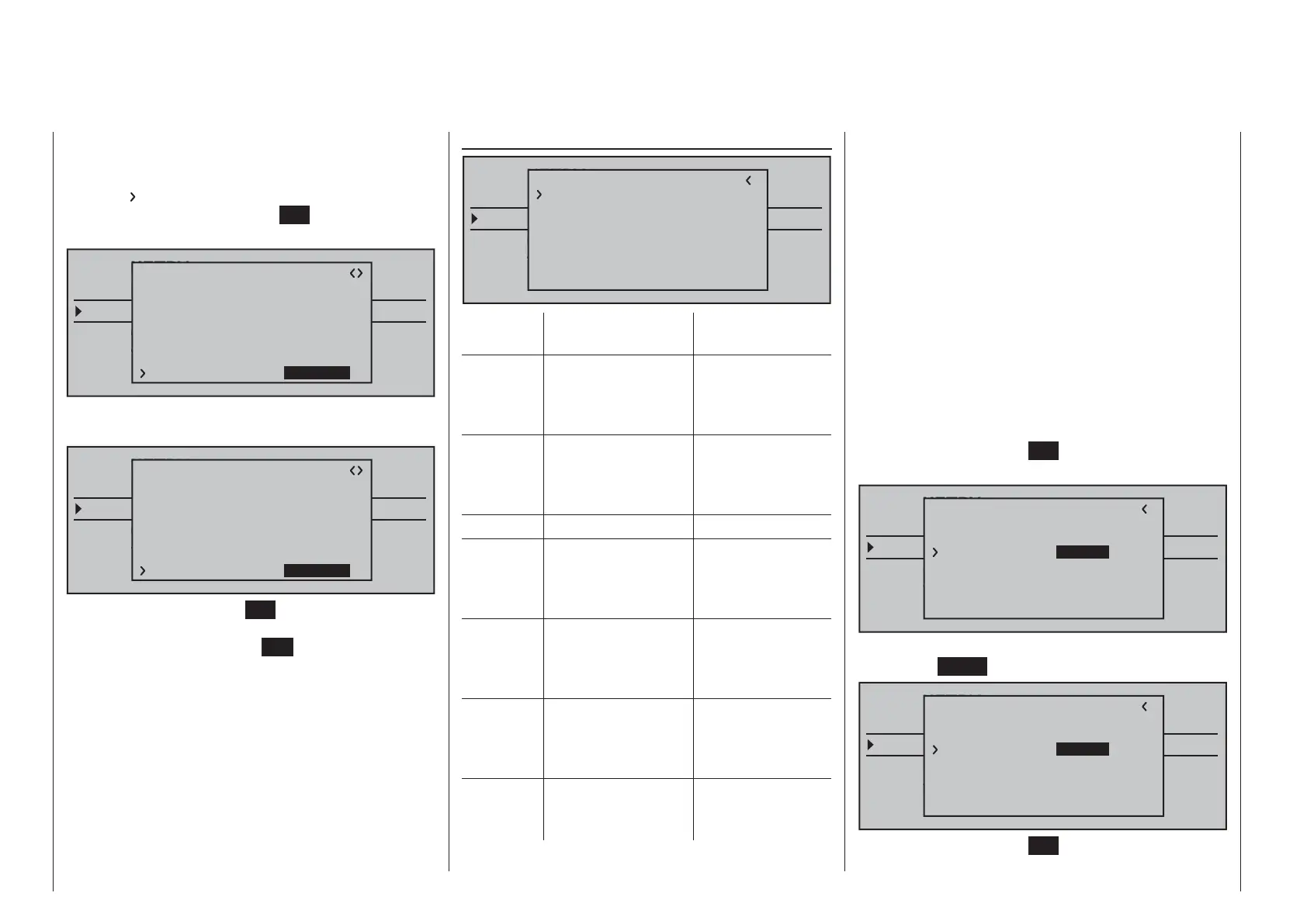
TELEMETRY
SETTING & DATAVIEW
SENSOR SELECT
RF STATUS VIEW
VOICE TRIGGER
TELEMETRI RCV
BIND. 1
RX CURVE
TYPE : A
CURVE1 CH : 02
TYPE : A
CURVE2 CH : 03
TYPE : B
CURVE3 CH : 04
5CH FUNCTION:SERVO
Now use one of the cd selection keys on the right
touch pad to select the alternative setting "SENSOR".
TELEMETRY
SETTING & DATAVIEW
SENSOR SELECT
RF STATUS VIEW
VOICE TRIGGER
TELEMETRI RCV
BIND. 1
RX CURVE
TYPE : A
CURVE1 CH : 02
TYPE : A
CURVE2 CH : 03
TYPE : B
CURVE3 CH : 04
5CH FUNCTION:SENSOR
Another tap on the center SET key of the right touch
pad will close the selection and, with appropriate
repetitive taps on the center
ESC key of the left touch
pad, a return to the transmitter's basic display is
accomplished.
RX SERVO TEST
TELEMETRY
SETTING & DATAVIEW
SENSOR SELECT
RF STATUS VIEW
VOICE TRIGGER
TELEMETRI RCV
BIND. 1
RX SERVO TEST
ALL–MIN : 1000sec
ALL–MAX : 2000sec
ALARM VOLT : 3.8V
TEST : STOP
ALARM TEMP–:–10°C
ALARM TEMP+: 70°C
CH OUT TYPE:ONCE
Value Explanation Possible
settings
ALL-MAX Servo travel on the
"+" side for all servo
outputs for the
servo test
1500 … 2000 μs
ALL-MIN Servo travel on the
"-" side for all servo
outputs for the
servo test
1500 … 1000 μs
TEST Test procedure START / STOP
ALARM
VOLT
Alarm threshold
of the receiver
undervoltage
warning
3.0 … 6.0 V
factory setting:
3.8 V
ALARM
TEMP+
Alarm threshold for
excessively high
temperature of the
receiver
50 … 80 °C
Factory setting:
70 °C
ALARM
TEMP–
Alarm threshold
for excessively low
temperature of the
receiver
-20 … +10 °C
Factory setting:
-10 °C
CH
OUTPUT
TYPE
Channel sequence ONCE, SAME,
SUMI, SUMO
ALL-MAX (servo travel on the "+" side)
In this line you set the maximum servo travel on the
plus side of the control travel for the servo test.
2000 μs corresponds to the full throw; 1500 μs
corresponds to the neutral position.
Make sure that the servos do not overrun
mechanically during the test routine.
ALL-MIN (servo travel on the "-" side)
You adjust the maximum servo travel on the minus
side of the control path for the servo test in this line.
1000 μs corresponds to the full throw; 1500 μs
corresponds to the neutral position.
TEST
You start and stop the servo test integrated in the
receivers in this line.
A brief tap on the center
SET key of the right touch
pad will open the entry fi eld:
TELEMETRY
SETTING & DATAVIEW
SENSOR SELECT
RF STATUS VIEW
VOICE TRIGGER
TELEMETRI RCV
BIND. 1
RX SERVO TEST
ALL–MIN : 1000sec
ALL–MAX : 2000sec
ALARM VOLT : 3.8V
ALARM TEMP–:–10°C
ALARM TEMP+: 70°C
CH OUT TYPE:ONCE
TEST : STOP
Now, with one of the selection keys of the right touch
pad, select
START:
TELEMETRY
SETTING & DATAVIEW
SENSOR SELECT
RF STATUS VIEW
VOICE TRIGGER
TELEMETRI RCV
BIND. 1
RX SERVO TEST
ALL–MIN : 1000sec
ALL–MAX : 2000sec
ALARM VOLT : 3.8V
ALARM TEMP–:–10°C
ALARM TEMP+: 70°C
CH OUT TYPE:ONCE
TEST : START
A brief tap on the center SET key of the right touch
pad will now start the test run. The input fi eld is

 Loading...


